API6D Valve configurations, Design, Pressure and temperature rating, Sizes
6.2 Valve configurations
6.2.1 Full-opening valves
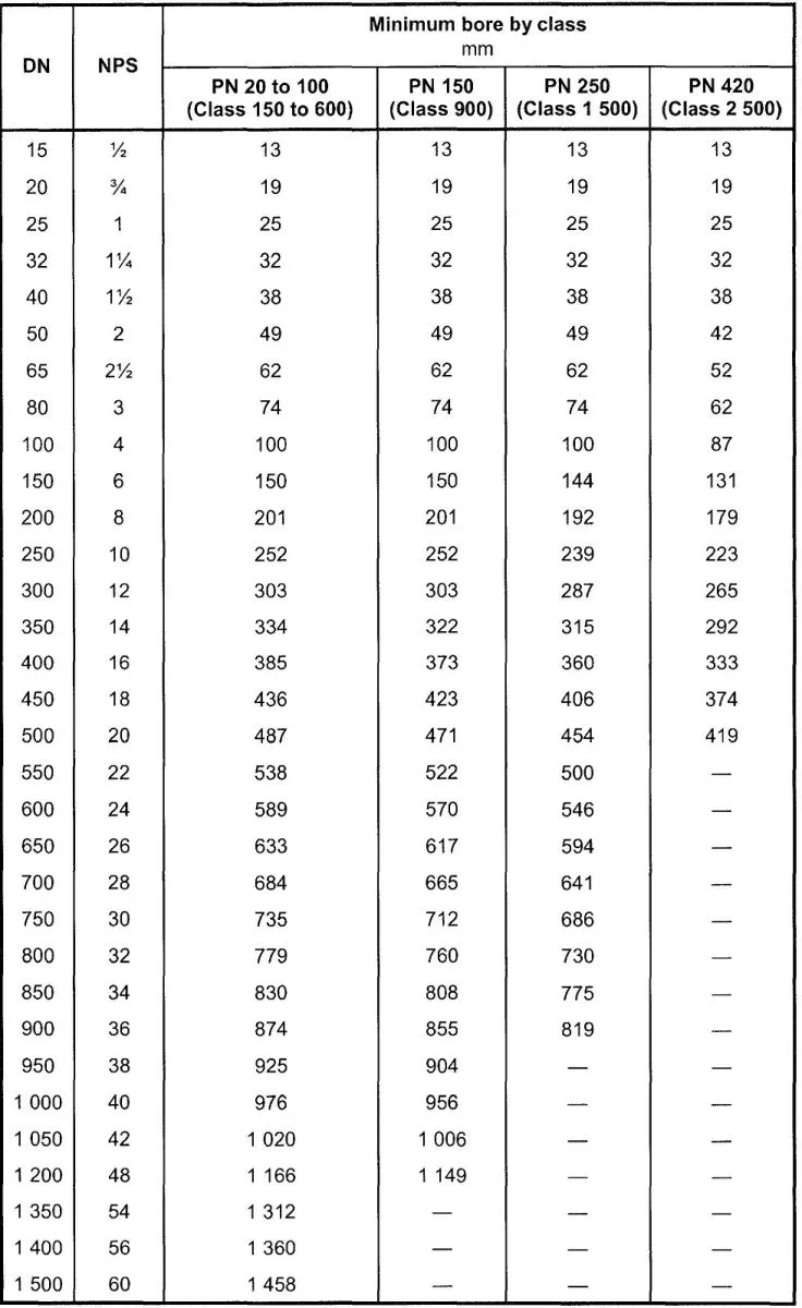
Full-opening flanged-end valves shall be unobstructed in the fully opened position and shall have an internal bore as specified in Table 1. There is no restriction on the upper limit of valve bore sizes. Full-opening through-conduit valves shall have a circular bore in the obturator that allows a sphere to pass with a nominal size not less than that specified in Table 1.
Welding-end valves can require a smaller bore at the welding end to mate with the pipe. Valves with a non-circular opening through the obturator shall not be considered full opening.
6.2.2 Reduced-opening valves
Reduced-opening valves with a circular opening through the obturator shall be supplied with a minimum bore as follows, unless otherwise specified: valves ON 300 (NPS 12) and below: one size below nominal size of valve with bore according to Table 1; valves ON 350 (NPS 14) to ON 600 (NPS 24): two sizes below nominal size of valve with bore according to Table 1; valves above ON 600 (NPS 24): by agreement. EXAMPLE A DN 400 (NPS 16) - PN 250 (class 1500) reduced-opening ball valve has a minimum bore of 287 mm. Reduced-opening valves with a non-circular opening through the obturator shall be supplied with a minimum opening by agreement.
7 Design
7.1 Design standards and calculations
Pressure-containing parts, including bolting, shall be designed with materials specified in Clause 8. Design and calculations for pressure containing elements shall be in accordance with an internationally recognized design code or standard with consideration for pipe loads, operating forces, etc. The choice of standard shall be by agreement.
NOTE 1 Examples of internationally recognized design codes or standards are ASME Section VIII Division 1 or Division 2, ASME 816.34, EN 12516-1 and EN 13445-3.
The allowable stress values shall be consistent with the selected design code or standard. If the selected design code or standard specifies a test pressure less than 1,5 times the design pressure, then the design pressure for the body calculation shall be increased such that the hydrostatic test pressure in 11.3 can be applied.
NOTE 2 Some design codes or standards require a consistent and specific application of requirements for fabrication and testing, including NDE.
7.2 Pressure and temperature rating
The nominal pressure (PN) class or the ASME rating class shall be used for the specification of the required pressure class.
Valves covered by this International Standard shall be furnished in one of the following classes:
Pressure-temperature ratings for PN-rated valves shall be in accordance with the applicable rating table for the appropriate material group in EN 1092-1.
If intermediate design pressures and temperatures are specified by the purchaser, the pressure-temperature rating shall be determined by linear interpolation.
Pressure-temperature ratings for valves made from materials not covered by ASME 816.34 and EN 1092-1
shall be determined from the material properties in accordance with the applicable design standard.
NOTE Non-metallic parts can limit maximum pressures and minimum and maximum operating temperatures.
The maximum operating pressure at the minimum and maximum operating temperatures shall be marked on the nameplate.
7.3 Sizes
Valves constructed to this International Standard shall be furnished in nominal sizes as listed in Table 1.
NOTE In this International Standard, DN sizes are stated first followed by the equivalent NPS size between brackets.
Except for reduced-opening valves, valve sizes shall be specified by the nominal sizes (ON) or nominal pipe size (NPS).
Reduced-opening valves with a circular opening shall be specified by the nominal size of the end connections and the nominal size of the reduced opening in accordance with Table 1.
EXAMPLE 1 A ON 400 - PN 20 valve with a reduced 303 mm diameter circular opening shall be specified as ON 400 (NPS 16) x ON 300 (NPS 12).
Reduced-opening valves with a non-circular opening and reduced-opening check valves shall be designated as reduced-bore valves and specified by the nominal size corresponding to the end connections followed by
the letter "R".
EXAMPLE 2 Reduced-bore valve with ON 400 (NPS 16) end connections and a 381 mm x 305 mm rectangular opening shall be specified as 400R.
6.2.1 Full-opening valves
Full-opening flanged-end valves shall be unobstructed in the fully opened position and shall have an internal bore as specified in Table 1. There is no restriction on the upper limit of valve bore sizes. Full-opening through-conduit valves shall have a circular bore in the obturator that allows a sphere to pass with a nominal size not less than that specified in Table 1.
Welding-end valves can require a smaller bore at the welding end to mate with the pipe. Valves with a non-circular opening through the obturator shall not be considered full opening.
6.2.2 Reduced-opening valves
Reduced-opening valves with a circular opening through the obturator shall be supplied with a minimum bore as follows, unless otherwise specified: valves ON 300 (NPS 12) and below: one size below nominal size of valve with bore according to Table 1; valves ON 350 (NPS 14) to ON 600 (NPS 24): two sizes below nominal size of valve with bore according to Table 1; valves above ON 600 (NPS 24): by agreement. EXAMPLE A DN 400 (NPS 16) - PN 250 (class 1500) reduced-opening ball valve has a minimum bore of 287 mm. Reduced-opening valves with a non-circular opening through the obturator shall be supplied with a minimum opening by agreement.
Table 1 - Minimum bore for full-opening valves
7 Design
7.1 Design standards and calculations
Pressure-containing parts, including bolting, shall be designed with materials specified in Clause 8. Design and calculations for pressure containing elements shall be in accordance with an internationally recognized design code or standard with consideration for pipe loads, operating forces, etc. The choice of standard shall be by agreement.
NOTE 1 Examples of internationally recognized design codes or standards are ASME Section VIII Division 1 or Division 2, ASME 816.34, EN 12516-1 and EN 13445-3.
The allowable stress values shall be consistent with the selected design code or standard. If the selected design code or standard specifies a test pressure less than 1,5 times the design pressure, then the design pressure for the body calculation shall be increased such that the hydrostatic test pressure in 11.3 can be applied.
NOTE 2 Some design codes or standards require a consistent and specific application of requirements for fabrication and testing, including NDE.
7.2 Pressure and temperature rating
The nominal pressure (PN) class or the ASME rating class shall be used for the specification of the required pressure class.
Valves covered by this International Standard shall be furnished in one of the following classes:
- PN 20 (class 150);
- PN 50 (class 300);
- PN 64 (class 400);
- PN 100 (class 600);
- PN 150 (class 900);
- PN 250 (class 1500);
- PN 420 (class 2500).
Pressure-temperature ratings for PN-rated valves shall be in accordance with the applicable rating table for the appropriate material group in EN 1092-1.
If intermediate design pressures and temperatures are specified by the purchaser, the pressure-temperature rating shall be determined by linear interpolation.
Pressure-temperature ratings for valves made from materials not covered by ASME 816.34 and EN 1092-1
shall be determined from the material properties in accordance with the applicable design standard.
NOTE Non-metallic parts can limit maximum pressures and minimum and maximum operating temperatures.
The maximum operating pressure at the minimum and maximum operating temperatures shall be marked on the nameplate.
7.3 Sizes
Valves constructed to this International Standard shall be furnished in nominal sizes as listed in Table 1.
NOTE In this International Standard, DN sizes are stated first followed by the equivalent NPS size between brackets.
Except for reduced-opening valves, valve sizes shall be specified by the nominal sizes (ON) or nominal pipe size (NPS).
Reduced-opening valves with a circular opening shall be specified by the nominal size of the end connections and the nominal size of the reduced opening in accordance with Table 1.
EXAMPLE 1 A ON 400 - PN 20 valve with a reduced 303 mm diameter circular opening shall be specified as ON 400 (NPS 16) x ON 300 (NPS 12).
Reduced-opening valves with a non-circular opening and reduced-opening check valves shall be designated as reduced-bore valves and specified by the nominal size corresponding to the end connections followed by
the letter "R".
EXAMPLE 2 Reduced-bore valve with ON 400 (NPS 16) end connections and a 381 mm x 305 mm rectangular opening shall be specified as 400R.