LET US DISCUSS THE WAY A PNEUMATIC VALVE POSITIONER WORKS

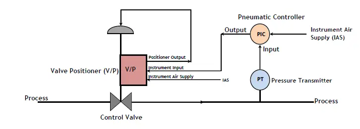
A valve positioner could be set either to direct-acting or reverse-acting. An immediate-acting valve positioner transmits an elevated output signal towards the control valve because the input signal into it increases. A reverse-acting valve positioner, transmits a low output signal because the input signal into it increases.
The way the Pneumatic Valve Positioner Works
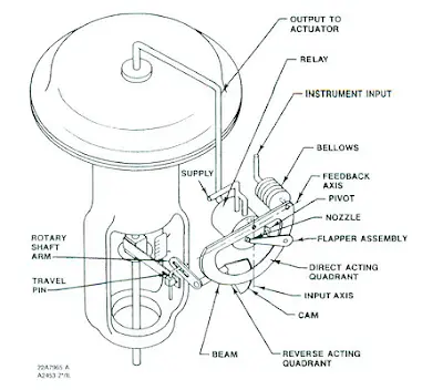
The schematic below is an immediate-acting Fisher 3582G pneumatic valve positioner:

As proven within the diagram, the valve positioner is mounted on a diaphragm-actuated sliding stem control valve. The availability pressure is linked to a pneumatic relay. A set hole restriction within the relay limits flow towards the nozzle so that once the flapper isn't restricting the nozzle, air can bleed out quicker than has been provided.
The input signal in the device is attached to the bellows. Once the input signal increases, the bellows expand and moves the beam. The beam pivots concerning the input axis moving the flapper nearer to the nozzle. The nozzle pressure increases and thru the pneumatic relay action boosts the output pressure towards the valve actuator. The elevated output pressure towards the actuator causes the actuator stem to maneuver downward. Stem movement will be given to the beam using a cam. Because the cam rotates, the beam pivots concerning the feedback axis to maneuver the flapper slightly from the nozzle. The nozzle pressure decreases and cuts down on the output pressure towards the actuator. Stem movement continues backing the flapper from the nozzle until equilibrium is achieved.
Once the input pressure decreases, the bellows contracts (helped by an interior range spring) and also the beam pivots concerning the input axis to maneuver the flapper from the nozzle. Nozzle pressure decreases and also the pneumatic relay permits the discharge of diaphragm casing pressure to atmosphere resulting in the actuator stem to maneuver upward. With the cam, stem movement is given to the beam to re-squeeze flapper nearer to the nozzle. When equilibrium the weather is achieved, stem movement stops and also the flapper lies to avoid any more reduction in diaphragm situation pressure.
Inside a reverse-acting valve positioner, exactly the same fundamental operating principle above applies with the exception that because the input signal increases, the diaphragm casing pressure is decreased. A decreasing input signal causes a rise in pressure towards the diaphragm casing from the control valve.
How you can Change Valve Positioner Action from the 3582G Pneumatic Valve Positioner

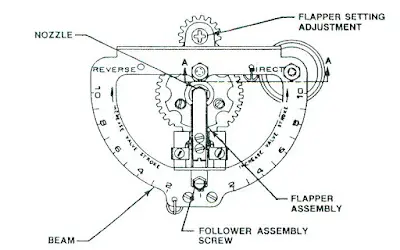
Positioner Beam (Photo Credit: Fisher)
The positioning of the flapper set up around the beam determines if the valve positioner will behave as direct-acting or reverse-acting.
As proven within the diagram above, the beam is split into quadrants. The direct acting quadrant is labelled DIRECT and also the reverse-acting quadrant is labelled REVERSE. To alter the valve positioner action, simply slowly move the flapper set up towards the opposite quadrant from the beam.
Valve Co. for Control Valves
Whether you possess an emergency situation or you have further queries about our control valve, please call us sales@shinjovalve.com.