The globe valve design and kinds
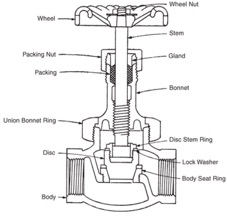
Globe valve is really a straight line motion valve accustomed to on-off service and throttling service (regulate fluid flow). The structural elements of the globe valve are proven on Figure 1 and become just like individuals of gate valves.
Number of materials are for sale to globe valve physiques, most generally are created surefire, cast steel, forged steel, and corrosion-resistant alloys while mostly using screwed, flanged, and welded body-finish connections.
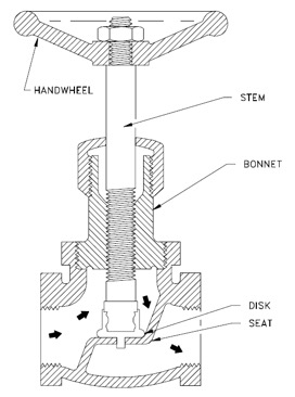
Figure 1. Style of the globe valve
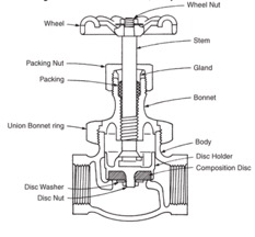
The globe valve come with different bonnets (union, screwed in and screwed on, flanged, pressure sealed etc.) and stems (inside screw, outdoors screw, sliding stem), but many of design variations range from disc (plug) design. Besides conventional disc other common disc designs are tapered plug disc and composite disc. Globe valve seats are generally integral with or screwed in to the valve body. Many globe valves have backseats, then when the valve is fully open, the disk seats from the backseat which prevents system pressure from building from the valve packing.
Globe valve come with the disk that closes against or perhaps in exactly the same direction of fluid flow. Once the disk closes within the same direction of flow, the kinetic energy from the fluid aids closing but impedes opening and the other way around. This characteristic is more suitable with other designs when quick-acting stop valves are essential.
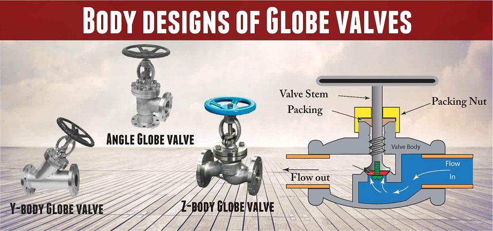
In regards to the globe valves valve body design, you will find primary three body designs for globe valves: Z-type, Y-type and position type. Proven around the Figure 1. may be the simplest and many common for water applications may be the Z-body design, also referred to as an upright-through globe valve.
Y-body design valves, also referred to as mix-flow globe valves design cuts down on the ruthless drop natural in globe valves. The seat and stem are angled at roughly 45° using the media flow, for any straighter flow path at full opening. The Y-design also keeps the stem, bonnet, and packing inside a relatively pressure-resistant envelop.
Position globe valves, highlighted on Figure 3. are made so the inlet and outlet are verticle with respect. They are utilised for transferring flow from vertical to horizontal. Fluid has the capacity to flow finished merely a single 90° turn and discharge downward more symmetrically compared to discharge in the Z-type.
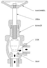
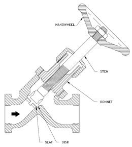
Figure 3. Left: Angel globe valve. Right: Y-type globe valve
Operating principle
The operation - flow via a globe valve follows a altering course: the fluid enters the valve parallel towards the valve port after two 90° turns leaves the valve again parallel towards the valve port.
As proven in Figure 1, the globe valve seating is parallel towards the type of flow, disk (plug) could be totally taken off the flow path when valve is fully open, or it may completely close the flow path when valve is within closed position.
Globe valve regulates fluid flow by different how big the main harbour opening by which the fluid flows. This is done by different the positioning of the disc - verticle with respect movement from the disk (plug) from and toward the valve seat. All contact between your seat and also the disc ends when flow begins. This characteristic provides the globe valve good throttling ability, which allows its use within controlling flow.
Application and benefits
Globe valve may be used in a multitude of industrial applications.
A composition disc isn't suggested for throttling service thus is extremely considered for dependable, tight seating for hard-to-hold fluids, for example gas and compressed air. They are able to usually tolerate the embedment of dirt without dripping.
Due to its configuration, the tapered plug disk provides better throttling than other globe valve designs. The flow-control element includes a wide seating connection with the tapered seat. The configuration produces a directly proportionate relation of size seat opening to the amount of turns from the hands wheel and permits close flow regulation. All contact between your seat and also the disc ends when flow begins. This can be a distinct advantage for that throttling of flow having a minimum of wire drawing and seat erosion.
The traditional disc design is suggested for positive shut-from fluids however is not suggested for throttling service.
Position body design has particular advantage that it may work as both a valve along with a piping elbow. For moderate conditions of pressure, temperature, and flow, the position valve carefully resembles the standard globe. The position valve's discharge the weather is favorable regarding fluid dynamics and erosion.
The Y-design provides stem, bonnet, and packing in pressure-resistant envelop making Y-design appropriate for top pressures along with other severe services Globe valves employed for steam applications are mainly welded in to the system, the very best-entry maintenance makes globe valves well suited for the ability industry. Also, the disc and seat could be rapidly and simply reseated or replaced, making using globe valves well suited for applications where frequent maintenance is needed.
