Valve Basic knowledges
Valves are mechanical devices that controls the flow and pressure inside a system or process. They're essential aspects of a piping system that conveys fluids, gases, vapors, slurries etc..
Various kinds of valves can be found: gate, globe, plug, ball, butterfly, check, diaphragm, pinch, pressure relief, control valves etc. All these types has numerous models, each with various features and functional abilities. Some valves are self-operated while some by hand or by having an actuator or pneumatic or hydraulic is operated.
Functions from Valves are:
Stopping and starting flow
Reduce or increase a flow
Controlling the direction of flow
Regulating a flow or process pressure
Relieve a pipe system of a certain pressure

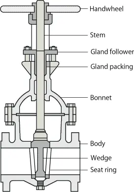
No matter type, all valves possess the following fundamental parts: your body, bonnet, trim (internal elements), actuator, and packing. The fundamental areas of a valve are highlighted within the image around the right.
Valve Body
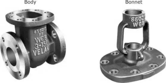
Your body, the very first pressure boundary of the valve, resists fluid pressure loads from connecting piping. It receives inlet and outlet piping through threaded, screwed, or welded joints.
The valve-body ends are made to connect the valve towards the piping or equipment nozzle by various kinds of finish connections, for example butt or socket welded, threaded or flanged.
Valve physiques are cast or forged in a number of forms and every component possess a specific function and built inside a material appropriate for your function.

Valve Bonnet
A bonnet functions like a cover around the valve body, is cast or forged of the identical material because the body. It's generally attached to the body with a threaded, screwed, or welded joint. During output of the valve, the interior components, for example stem, disk etc., they fit in to the body and so the bonnet is mounted on hold every part together inside.
In every case, the attachment from the bonnet towards the is considered a pressure boundary. Which means that the weld joint or bolts that connect the bonnet towards the body are pressure-retaining parts. Valve bonnets, although essential for many valves, represent a reason to be concerned. Bonnets can complicate the output of valves, increase valve size, represent a substantial cost part of valve cost, and therefore are a resource for potential leakage.
Valve Trim
A Valve's trim performance is dependent upon the disk and seat interface and also the relation from the disk position towards the seat. Due to the trim, fundamental motions and flow control are possible. In rotational motion trim designs, the disk slides carefully beyond the seat to make a alternation in flow opening. In straight line motion trim designs, the disk lifts perpendicularly from the seat to ensure that an annular hole seems.
Valve trim parts might be built of varied materials due to the different qualities required to withstand different forces and types of conditions. Bushings and packing glands don't feel the same forces and types of conditions just like the valve disc and seat(s).
Flow-medium qualities, chemical composition, pressure, temperature, flow rate, velocity and viscosity are the important factors when deciding on appropriate trim materials. Trim materials might or might not function as the same material because the valve body or bonnet.
Valve Disk and Seat(s)
Disk
Disks are often forged, as well as in some designs, hard surfaced to supply good put on qualities. Most valves are named, the style of their disks.
Seat(s)
To enhance the put on-resistance from the seal rings, the top is frequently hard-faced by welding after which machining the contact top of the seal ring. An excellent surface finish from the sitting area is essential permanently sealing once the valve is closed. Seal rings aren't usually considered pressure boundary parts since the body has sufficient wall thickness to resist design pressure without relying upon the thickness from the seal rings.
Valve Stem
Stems are often forged, and attached to the disk by threaded or any other techniques. To avoid leakage, in the seal, an excellent surface finish from the stem is essential.
You will find five kinds of valve stems:
Rising Stem with Outdoors Screw and Yoke
The outside of the stem is threaded, as the area of the stem within the valve is smooth. The stem threads are isolated in the flow medium through the stem packing. Two variations of those designs can be found one using the handwheel connected to the stem, to allow them to rise together, and yet another having a threaded sleeve that triggers the stem to increase with the handwheel. This kind of valve is shown by "O. S. & Y." is a very common the perception of NPS 2 and bigger valves.
Rising Stem with Inside Screw
The threaded area of the stem is within the valve body, and also the stem packing across the smooth section that's uncovered towards the atmosphere outdoors. Within this situation, the stem threads are in touch with the flow medium. When rotated, the stem and also the handwheel to increase together to spread out the valve.
Non Rising Stem with Inside Screw
The threaded area of the stem is within the valve and doesn't rise. The valve disc travels across the stem, just like a nut when the stem is rotated. Stem threads are uncovered towards the flow medium, and therefore, are exposed towards the impact. That's the reason this model can be used when space is restricted to permit straight line movement, and also the flow medium doesn't cause erosion, corrosion or abrasion from the stem material.
Sliding Stem
This valve stem doesn't rotate or turn. It slides out and in the valve to spread out or close the valve. This design can be used in hands-operated lever rapid opening valves. It's also utilized in control valves are run by hydraulic or pneumatic cylinders.
Rotary Stem
This can be a generally used model in ball, plug, and Butterfly valves. One fourth-turn motion from the stem open or close the valve.
Within the primary Menu "Valves" you'll find some links to detailed (large) pictures of Rising and NON Rising Stem valves.
Valve Stem Packing
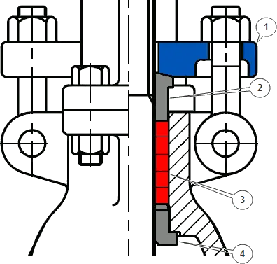
For any reliable seal between your stem and also the bonnet, a gasket is required. This really is known as a Packing, which is fitted with e.g. the next components:
Gland follower, a sleeve which compresses the packing, with a gland in to the so known as stuffing box.
Gland, a type of bushing, which compressed de packing in to the stuffing box.
Stuffing box, a chamber where the packing is compressed.
Packing, obtainable in several materials, like Teflon?, elastomeric material, " floating " fibrous material etc..
An essential part of the existence duration of a valve may be the sealing set up. Just about all valves, like standard Ball, Globe, Gate, Plug and Butterfly valves get their sealing set up based on shear pressure, friction and tearing.
Therefore valve packaging should be correctly happen, to avoid harm to the stem and fluid or gas loss. Whenever a packing is simply too loose, the valve will leak. When the packing is simply too tight, it'll modify the movement and possible harm to the stem.
TYPICAL SEALING ASSEMBLY

1. Gland Follover 2. Gland 3. Stuffing Box with Packing 4. Back Seat
Valve Yoke and Yoke Nut
Yoke
Yoke Nut
A Yoke nut is definitely an internally threaded nut and it is put into the top of the a Yoke through which the stem passes. Inside a Gate valve e.g., the Yoke nut is switched and also the stem travels up or lower. Within the situation of Globe valves, the nut is bound and also the stem is rotated through it.
Valve Actuator
Hands-operated valves are often outfitted having a handwheel connected to the valve's stem or Yoke nut that is rotated clockwise or counter clockwise to shut or open a valve. Globe and gate valves are opened up and closed in this manner.
Hands-operated, quarter turn valves, for example Ball, Plug or Butterfly, includes a lever for actuate the valve.
You will find applications where it's not possible or desirable, to actuate the valve by hand by handwheel or lever. These applications include:
Large valves that must definitely be operated against high hydrostatic pressure
Valves they ought to be operated from the remote location
Once the here we are at opening, closing, throttle or by hand manipulating the valve is longer, than needed by system-design criteria
These valves are often outfitted by having an actuator.
An actuator within the largest definition is really a device that creates straight line and rotary motion of an origin of power under the act of an origin of control.
Gear Actuators
Motor Unit Actuators
Pneumatic Actuators
Hydraulic Actuators
Solenoid Actuators
To learn more about Actuators see primary Menu "Valves" -Valve Actuators-
Classification of Valves
The next are the generally used valve classifications, according to mechanical motion:
Rotary Motion Valves. Once the valve-closure member travels along an angular or circular path, as with butterfly, ball, plug, eccentric- and Swing Check Valves, the valves are known as rotary motion valves.
Quarter Turn Valves. Some rotary motion valves require roughly one fourth turn, through 90°, motion from the stem to visit fully open from the fully closed position or the other way around.
CLASSIFICATION OF VALVES BASED ON MOTION
| VALVE TYPES | LINEAR MOTION | ROTARY MOTION | QUARTER TURN |
| GATE | YES | NO | NO |
| GLOBE | YES | NO | NO |
| PLUG | NO | YES | YES |
| BALL | NO | YES | YES |
| BUTTERFLY | NO | YES | YES |
| SWING CHECK | NO | YES | NO |
| DIAPHRAGM | YES | NO | NO |
| PINCH | YES | NO | NO |
| SAFETY | YES | NO | NO |
| RELIEF | YES | NO | NO |
| VALVE TYPES | LINEAR MOTION | ROTARY MOTION | QUARTER TURN |
Valve Types Straight line Motion Rotary Motion Quarter Turn
Class Ratings
Summary
In this article are defined numerous fundamental information from valves.
Since you may have experienced within the primary Menu "Valves", you'll find also details about several and frequently applied valves in Petro and chemical industry.
It can provide you with an impact, and good knowledge of the variations between your various valves, and just how these variations modify the valve function. It can help to some proper use of each kind of valve throughout the design and also the proper utilization of each kind of valve during operation.
Click this link to learn more about our valve ranges.
Next: Valve Material Application And It's History
Previous: What Is Safety Valve?