A valve positioner is the instrument mounted on a control valve that makes the valve go where the controller tells it to. It receives the control signal, measures the actual stem position through a feedback linkage, and raises or lowers the air pressure in the actuator until the two agree. Without one, the signal pressure goes straight to the actuator, and the valve position depends on friction and process forces as well as on the signal.
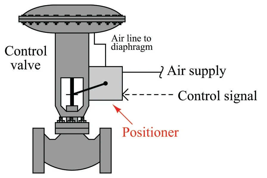
This page covers positioners for pneumatic actuators: what they do, how they work, the main types, and when one is needed. For the valve and actuator themselves, see our pneumatic control valve guide.
A spring-and-diaphragm actuator on its own is an open-loop device. A given air pressure should produce a given stem position, but three things get in the way:
- Packing friction makes the stem stick and then jump.
- The force of the process fluid on the plug changes with the pressure drop.
- A large actuator takes time to fill and empty through a small signal line.
A positioner closes a small control loop around the valve position. It has its own air supply at full pressure, so it can drive the actuator harder and faster than the signal alone. The process controller still controls the process; the positioner only guarantees that a 50% signal produces 50% travel.

Most positioners use the same sequence, whatever their construction.
- The controller sends a signal: 4 to 20 mA to an electro-pneumatic or digital positioner, or 20 to 100 kPa (3 to 15 psi) to a pneumatic one.
- Inside the positioner, the signal is turned into a force. A pneumatic positioner uses a bellows or diaphragm capsule; an electro-pneumatic positioner uses a coil and magnet.
- A feedback lever or cam connected to the valve stem produces an opposing force that is proportional to the stem position.
- If the two forces are unequal, a pilot stage admits supply air to the actuator or vents air from it. The pilot is a nozzle and flapper with a relay, or a spool valve.
- The stem moves and the feedback force changes. When the forces balance again, the pilot returns to neutral and the valve holds its position.
This is called a force-balance mechanism. A digital positioner does the same job differently: a position sensor and a microprocessor make the comparison, and the result drives the pilot stage.
| Type | Input signal | How it compares | Strengths | Limits |
|---|---|---|---|---|
| Pneumatic | 20 to 100 kPa (3 to 15 psi) air signal | Mechanical force balance | No electricity at the valve; simple | Needs a pneumatic signal; manual calibration |
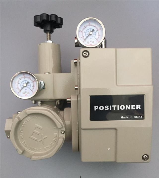
| Electro-pneumatic | 4 to 20 mA | Mechanical force balance with a built-in current-to-pressure stage | Works with electronic control systems; widely used | Manual zero and span adjustment |
| Digital (smart) | 4 to 20 mA, often with HART or a fieldbus | Position sensor and microprocessor | Automatic calibration, diagnostics, configurable characteristic | Higher cost; the digital functions need a compatible host |
Positioners are also classed by the actuator they drive. A single-acting positioner has one output, for a spring-return actuator. A double-acting positioner has two outputs, for a piston actuator without a spring. Linear positioners suit sliding-stem valves such as globe valves, and rotary positioners suit ball and butterfly valves.
Shinjo supplies the YT-1000 electro-pneumatic positioner, with a 4 to 20 mA DC input, on its control valves.
A positioner is the right answer in any of these cases:
- The control signal is 4 to 20 mA and the actuator is pneumatic.
- The actuator spring range is higher than the signal range, for example 40 to 200 kPa or 80 to 240 kPa.
- Packing friction is high, as with graphite packing or a bellows seal.
- The differential pressure is high or varies widely, so the force on the plug changes.
- The actuator is large and needs more air flow than a signal line can deliver.
- Two valves share one controller output in a split-range arrangement.
- The actuator is a double-acting piston with no spring.
On most new modulating valves a positioner is fitted as standard. The usual exception is a small, low-friction valve on a simple loop, which can run from a current-to-pressure converter alone.
An I/P converter turns a 4 to 20 mA signal into a 20 to 100 kPa air signal and nothing more. It has no connection to the valve stem, so it cannot know whether the valve has reached the position the signal asked for. A positioner has that feedback. An electro-pneumatic positioner contains an I/P stage and the feedback mechanism in one housing.
A direct-acting positioner raises its output pressure as the input signal rises. A reverse-acting positioner lowers its output as the signal rises. The action is chosen together with the actuator action, so that the valve fails to the correct position and moves in the direction the controller expects.
In split-range control, one controller output drives two valves. One positioner is set to stroke its valve over 4 to 12 mA and the other over 12 to 20 mA.
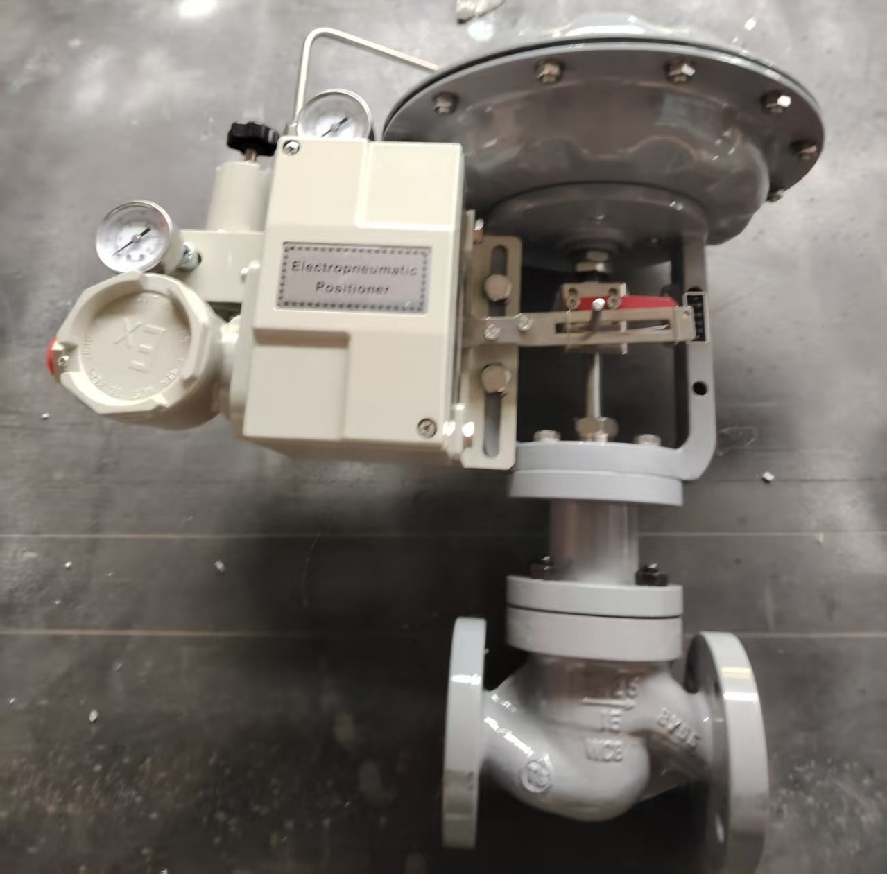
On a sliding-stem valve, the positioner is bolted to the actuator yoke and a feedback lever is clamped to the stem connector. The mounting interface for linear actuators is standardized in IEC 60534-6-1, often called NAMUR mounting. On a rotary valve, the positioner sits on top of the actuator and is coupled to the shaft; IEC 60534-6-2 and VDI/VDE 3845 define that interface.
Mounting quality decides accuracy. On most lever-type positioners, the feedback lever should be horizontal at mid-travel, and the linkage must have no play. A lever set at the wrong angle makes the travel non-linear, and a loose clamp shows up as hysteresis. Follow the manual for the model; the Shinjo HEP positioner manual is available in our downloads.
A mechanical positioner has two main adjustments. Zero sets the position at the bottom of the signal range, and span sets the travel across the whole range.
- Check the supply pressure, the air quality and the tightness of the linkage first.
- Apply 4 mA and adjust zero until the valve is just at its starting position.
- Apply 20 mA and adjust span until the valve reaches full travel.
- Repeat steps 2 and 3, because the two adjustments interact.
- Check 25%, 50% and 75% of the signal against the travel scale.
- Remove the air supply and confirm that the valve goes to its fail position.
A digital positioner runs this sequence itself in an automatic stroke routine. Do not calibrate a valve on a live process without isolation and the site's approved procedure.
| Symptom | Likely cause | What to check |
|---|---|---|
| Valve hunts or oscillates | Positioner gain too high for the actuator; high friction; oversized valve | Gain or damping setting, packing, valve sizing and controller tuning |
| Slow response | Low or restricted air supply; large actuator | Filter regulator setting, tubing size, a volume booster |
| Valve does not reach full travel | Span set wrong; supply pressure below the top of the spring range; slipped linkage | Span, supply pressure, lever and clamp |
| Position drifts, or air consumption rises | Worn pilot stage; leaks in the tubing or the actuator diaphragm | Leak test on the fittings, actuator diaphragm |
| No response to the signal | Nozzle or orifice blocked by dirty or wet air; failed coil; no supply | Air quality and filter, signal at the terminals, supply gauge |
Most positioner faults trace back to air quality. Feed the positioner clean, dry, oil-free instrument air through an air filter regulator.
- Input signal: 4 to 20 mA or a pneumatic signal, and any split range.
- Actuator type: single-acting or double-acting, and linear stroke or rotary angle.
- Supply pressure available.
- Direct or reverse action.
- Hazardous-area protection, intrinsically safe or flameproof, and the enclosure rating.
- Ambient temperature range.
- Position feedback: a 4 to 20 mA transmitter, limit switches or both.
- Communication protocol, if a digital positioner is wanted.
- Pressure gauges and the mounting kit.
For how the actuator under the positioner works, see What Is a Pneumatic Diaphragm Actuator?
A valve positioner is an instrument mounted on a control valve. It compares the control signal with the actual valve position and adjusts the air pressure in the actuator until the valve is where the signal says it should be.
No, but most modulating valves have one. It is needed when the signal is 4 to 20 mA, when the actuator spring range is higher than the signal range, when friction or process forces are high, or when the actuator is large or double-acting.
An I/P converter only changes a current signal into an air pressure. A positioner also measures the valve position and corrects it, so the valve reaches the requested travel even when friction or process forces resist.
It is a positioner that takes a 4 to 20 mA electrical signal and controls a pneumatic actuator. It combines a current-to-pressure stage and a position feedback mechanism in one unit.
A smart, or digital, positioner uses a position sensor and a microprocessor instead of a mechanical force balance. It can calibrate itself, report diagnostics and communicate over HART or a fieldbus.
On a sliding-stem valve it is mounted on the actuator yoke, with a lever linked to the stem. On a rotary valve it is mounted on top of the actuator and coupled to the shaft.
