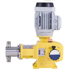
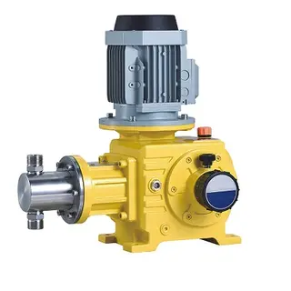
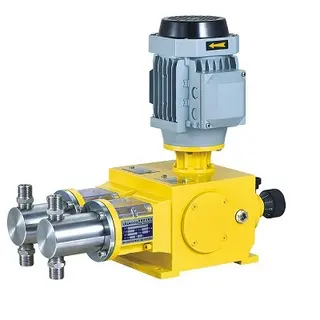
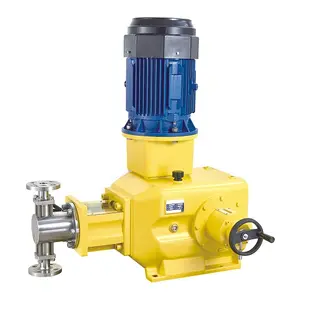
Key Specifications / Features
Model No.: SJ-MP-06 Hits: 213
Detail Information
Capacity range 92-6050lph, 8-500bar
Features:
1. Flow rate can be adjusted via unique adjusting mechanism from 0-100%
2. The adjustment can be carried when pump is in operation or at stop
3. The metering reproducibility is within ±1% from 30%-100% of the maximum output
4. Automatic operation is achieved by variable speed drive
5. Special application for high temperature or low temperature is available with cooling jacket or heating jacket
Materials:
1. Pump head: SS304, SS316
2. Pump case: Cast Iron
3. Plunger: SS316 coated with ceramic
4. Packing seal: PTFE and SS316 Ring
5. Valves: SS304,SS316
6. Valve ball: SS304,SS316, Ceramic
Power Supply:
380V 3 phase 50hz on standard, other voltage or 60hz on request; EX-proof motor is available on request.
| Model | 50Hz | 60 Hz | Pressure | Plunger Dia. (mm) |
Stroke Length (mm) |
Power kW(HP) |
Inlet&Outlet Size | Connection Size | |||||
| Flow (lph) |
Flow (gph) |
SPM | Flow (gph) |
Flow (lph) |
SPM | (Bar) | (Psi) | ||||||
| JDR 92/50 | 92 | 24 | 96 | 29 | 110 | 115 | 500 | 7250 | 20 | 60 | 5.5 (7.5) |
DN15 | DN15 WN Flange |
| JDR 145/32 | 145 | 38 | 46 | 174 | 320 | 4640 | 25 | ||||||
| JDR 190/18 | 190 | 50 | 60 | 228 | 250 | 3625 | 28 | ||||||
| JDR 240/20 | 240 | 63 | 76 | 288 | 200 | 2900 | 32 | ||||||
| JDR 430/11 | 430 | 114 | 136 | 516 | 110 | 1595 | 42 | DN20 | DN20 WN Flange |
||||
| JDR 520/9.0 | 520 | 137 | 165 | 624 | 90 | 1305 | 45 | ||||||
| JDR 650/8.0 | 650 | 172 | 206 | 780 | 80 | 1160 | 50 | ||||||
| JDR 780/6.5 | 780 | 206 | 247 | 936 | 65 | 943 | 55 | ||||||
| JDR 930/5.5 | 930 | 246 | 295 | 1116 | 55 | 798 | 60 | DN25 | DN25 RF Flange |
||||
| JDR 1100/4.6 | 1100 | 291 | 349 | 1320 | 46 | 667 | 65 | ||||||
| JDR 1300/4.0 | 1300 | 343 | 412 | 1560 | 40 | 580 | 70 | ||||||
| JDR 1480/3.5 | 1480 | 391 | 469 | 1776 | 35 | 508 | 75 | DN32 | DN32 RF Flange |
||||
| JDR 1700/3.0 | 1700 | 449 | 539 | 2040 | 30 | 435 | 80 | ||||||
| JDR 1920/2.8 | 1920 | 507 | 609 | 2304 | 28 | 406 | 85 | ||||||
| JDR 2150/2.4 | 2150 | 568 | 682 | 2580 | 24 | 348 | 90 | ||||||
| JDR 2400/2.2 | 2400 | 634 | 761 | 2880 | 2.2 | 32 | 95 | DN40 | DN40 RF Flange |
||||
| JDR 2680/2.0 | 2680 | 708 | 850 | 3216 | 18 | 261 | 100 | ||||||
| JDR 3250/1.6 | 3250 | 859 | 1030 | 3900 | 15 | 218 | 110 | ||||||
| JDR 3860/1.3 | 3860 | 1020 | 1224 | 4632 | 13 | 189 | 120 | ||||||
| JDR 4550/1.1 | 4550 | 1202 | 1443 | 5460 | 11 | 160 | 130 | DN50 | DN50 RF Flange |
||||
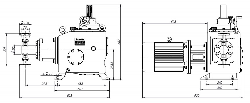
Installation Drawing:
