
- Nov 04, 2026
- Hits: 3
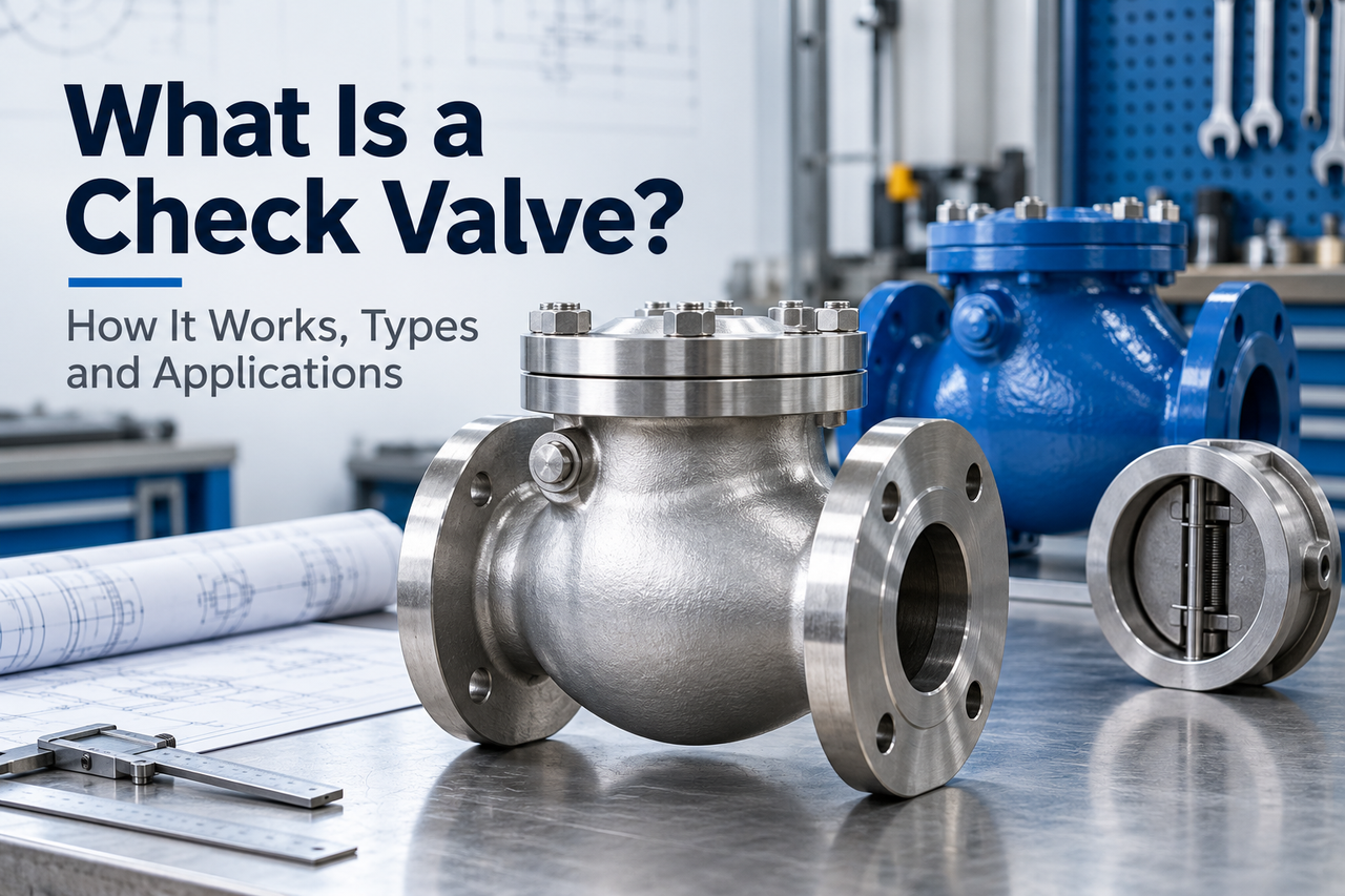
A check valve is an automatic valve that allows liquid or gas to flow in one direction and restricts flow in the opposite direction. Also called a non-return valve or one-way valve, it uses pressure and flow forces to move an internal closure onto or away from a seat. An ordinary check valve needs no electrical supply, air actuator or operator to perform that function.
You will find check valves on pump discharge lines, water distribution systems, compressed-air branches and process piping. Their purpose sounds simple, but the internal mechanism matters. A hinged disc in a large water main behaves differently from a small spring-loaded poppet in an instrument line. Both prevent reverse flow; they have different opening requirements, pressure losses and responses when a pump stops.
Choosing a check valve requires more than matching the pipe connection. Several terms need separating: cracking pressure and pressure rating, dual-plate and double-check valves, and reverse-flow prevention and positive isolation.
The main function of a check valve is to stop fluid from travelling back toward its source when the pressure relationship across the valve changes. During normal operation, the supply side drives fluid through. If the receiving side becomes the higher-pressure side, the closure moves toward its seat and restricts the return path.
Consider two pumps feeding one discharge header. One pump is running; the other is stopped. Without a suitable check valve in the stopped pump's branch, the operating pump can push water backward through that branch. A check valve provides an automatic boundary between the active header and the idle machine. It does not decide which pump should run or control the delivery pressure.
Other installations use the same function to retain liquid in a suction line, reduce drain-back after a pump stops, or discourage crossflow between branches. The Lee Company's introduction describes related uses in non-return, venting, and filling systems. The device can be very small, but the principle remains the same: a movable closure responds to forces generated by the fluid.
A check valve cannot perform every protective task in a piping system. It does not regulate downstream pressure like a pressure-reducing valve. It does not discharge excess pressure to a safe destination like a relief valve. Nor should an ordinary check valve be treated as the positive isolation needed to open equipment for maintenance. These are different jobs, even when the devices are installed close together.
Device | What causes it to operate? | Main job | What it does not establish by itself |
Ordinary check valve | Fluid forces, often assisted by gravity or a spring | Restrict reverse flow automatically | Positive maintenance isolation or overpressure relief |
Ball or gate isolation valve | Operator or actuator | Open or close a line on command | Automatic response to reverse flow |
Pressure-reducing valve | Downstream pressure acting through its control mechanism | Maintain a specified downstream pressure | A general substitute for a check valve |
Pressure-relief valve | Pressure reaching its specified opening condition | Release fluid to limit overpressure | Normal one-way delivery through a process line |
A check valve opens when the forward fluid forces are sufficient to move its closure away from the seat. As those forces decrease, the closure returns toward the seat under the influence of its spring, weight, geometry and the changing flow. Reverse differential pressure then tends to hold the closure against the seat. The timing and travel differ between designs.
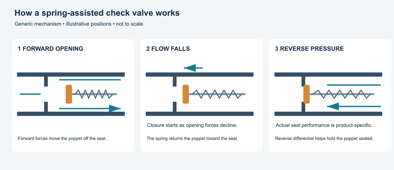
The inlet and outlet pressures both matter. For a simple comparison, define the forward pressure differential as inlet pressure minus outlet pressure. A large inlet gauge reading does not necessarily mean the valve will open: downstream pressure may be nearly as high.
In a spring-loaded valve, forward pressure acts over an effective area and produces a force that must overcome the spring preload and other resisting forces. In a gravity-assisted swing valve, the opening flow must move a hinged disc against its weight and mechanical resistance. The resulting opening is not always an immediate jump from fully closed to fully open. Many designs move progressively as the flow changes.
Once open, the valve still causes a pressure loss. Fluid passes around a poppet, ball or disc and through the available passages. The opening, body shape and fluid properties determine the loss at a particular flow. A valve advertised as having low resistance still needs enough operating energy to carry the required flow through its actual internal geometry.
When a pump slows or stops, the forces holding the closure open decrease. A return spring can begin moving the closure before substantial reverse flow develops. A freely hinged disc may follow a different trajectory because its position depends on flow, gravity and inertia.
This closing period is important in pumped systems. The moving water column does not become stationary just because electrical power has been removed from the motor. Flow decelerates according to the pipeline and system conditions, while the valve is moving at its own rate. The relationship between those two events determines how much reverse velocity can develop before the passage closes.
The goal is a closure response suited to that system. Calling every fast-closing valve harmful, or every slow-closing valve gentle, misses the interaction. A short-stroke spring-assisted design may close near flow reversal; a controlled final closing stage may be appropriate in another installation. The valve and pipeline need to be considered together.
When downstream pressure exceeds upstream pressure, the pressure difference usually pushes the closure more firmly onto its seat. A resilient seal may deform to establish contact; a metal seat depends on the condition and alignment of its mating surfaces. Debris, damage or a closure that cannot move freely can interrupt that contact.
“Closed” therefore describes a mechanical position, not an unlimited promise of zero leakage. The permissible leakage, test fluid, pressure difference and test method belong to the specified product and acceptance criteria. A valve that meets a particular water seat test has not automatically demonstrated the same performance with a low-pressure gas.
A small amount of movement or reverse displacement during closure is also different from sustained leakage after seating. That distinction helps when interpreting a brief pressure change at pump shutdown. Observing the whole event is more useful than assuming that any transient movement means a permanently failed seat.
Cracking pressure is the specified opening condition at which the first detectable forward flow occurs. For engineering comparisons, establish the corresponding pressure differential and the manufacturer's test conditions. Do not interpret it as an inlet gauge setting that applies regardless of outlet pressure. Swagelok's explanation of cracking and resealing makes the central distinction clear: the first indication of flow does not mean the valve is fully open.
Imagine a hypothetical valve with a nominal cracking differential of 0.15 bar. If inlet pressure is 3.20 bar gauge and outlet pressure is 3.00 bar gauge, the forward differential is 0.20 bar. That exceeds the assumed nominal opening differential. It does not establish the available flow rate, actual opening travel or pressure loss at full capacity.
Now raise both pressures: 8.00 bar gauge at the inlet and 7.90 bar gauge at the outlet. The forward differential is only 0.10 bar. Although the inlet pressure is much higher, this example provides less opening force from the pressure difference. Real cracking tolerances, temperature, installation position and friction still need to be considered. These figures illustrate arithmetic, not the performance of a Shinjo model.
Resealing pressure describes a separate closing or leakage condition. Some low-cracking-pressure products need a stated backpressure to achieve the specified seal. Other products reseal while a positive forward pressure remains. The tables illustrate why opening and resealing figures should be read separately rather than assumed equal.
Term | What it tells you | What it does not tell you |
Cracking pressure | When detectable forward flow begins under stated conditions | The flow available at that point |
Pressure drop at a stated flow | Energy lost across the operating valve | Whether a different flow will keep the closure stable |
Minimum stable operating flow | The lower operating boundary supplied for that design and duty | A universal velocity for every check valve |
Reseal condition | The pressure condition associated with the specified closing or leakage criterion | The same value as cracking pressure |
Pressure-temperature rating | The product's allowable service envelope under its applicable rating basis | Its opening pressure or acceptable surge response |
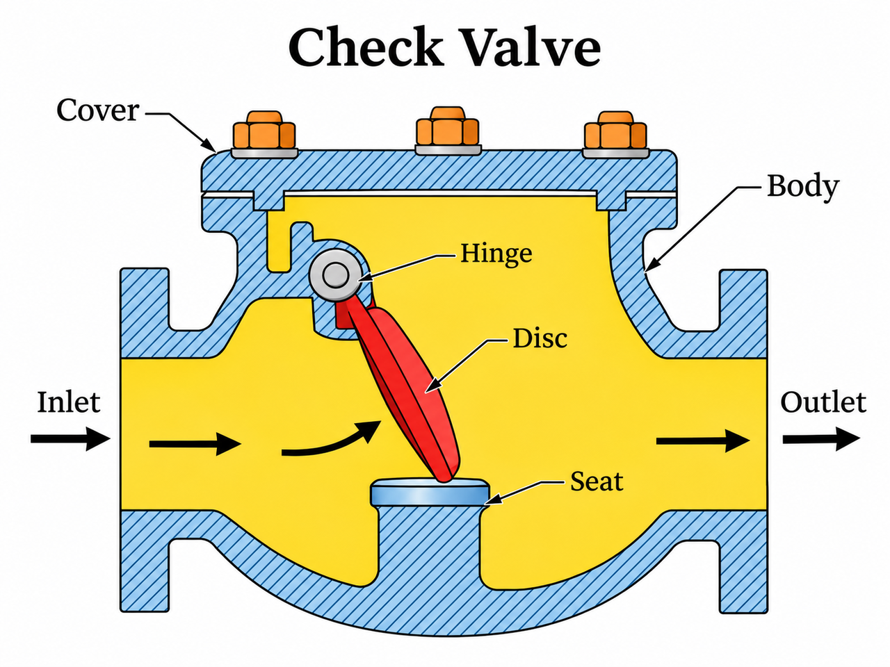
The body contains the fluid and forms the inlet, outlet and internal passage. It can be cast, forged or machined, with flanged, threaded, welded or other connections. The outside shape gives useful clues, but it does not reveal every internal detail. Two valves with similar flanges can have quite different flow paths and closures.
A removable cover or bonnet provides access to the internals on serviceable designs. Its bolting and gasket are part of the pressure boundary. Compact wafer valves may have no large removable cover, and some small inline products are not intended for field disassembly. Access arrangements influence how the valve can be inspected and how much space it needs in service.
The closure is the part that moves to interrupt reverse flow. A swing valve uses a hinged disc. A lift valve uses a guided disc or piston. A ball check uses a sphere, while a duckbill uses flexible lips. These shapes affect moving mass, travel and the route available to fluid.
The closure also carries sealing and wear surfaces. A rubber-coated ball, a metal disc and an elastomeric poppet should not be compared only by their body materials. The fluid contacts the moving element as well as the shell, and any coating or soft sealing layer has its own compatibility limits.
The seat is the stationary surface against which the closure seals. It may be machined into the body, fitted as a replaceable ring, or combined with a resilient insert. Metal seating and resilient seating are construction choices, not separate one-way operating principles.
A soft seat can help achieve a specified low-leakage performance, but its chemical and temperature limits can govern the whole assembly. A metal seat may suit a demanding thermal duty while accepting a different leakage criterion. Neither description alone establishes suitability. Seat finish, contact condition and the specified test requirements remain relevant.
A hinge constrains a disc to rotate; a guide constrains a piston or poppet to translate. These parts keep the closure aligned with its seat. Excessive wear, deposits or binding can affect movement even if the pressure-containing body remains sound.
A spring provides a closing force in many compact and short-stroke designs. A counterweight changes the torque acting on a rotating disc. A damper controls part of the motion. These accessories serve different purposes: adding weight is not the same as damping, and a damper setting cannot be selected from the pipe diameter alone.
The following names describe widely used mechanisms and application arrangements. They overlap. “Spring-loaded” describes a closing feature, “wafer” describes a compact installation form, and “foot valve” describes a suction-end assembly. A valve can therefore be both spring-loaded and wafer-pattern without becoming two different products.
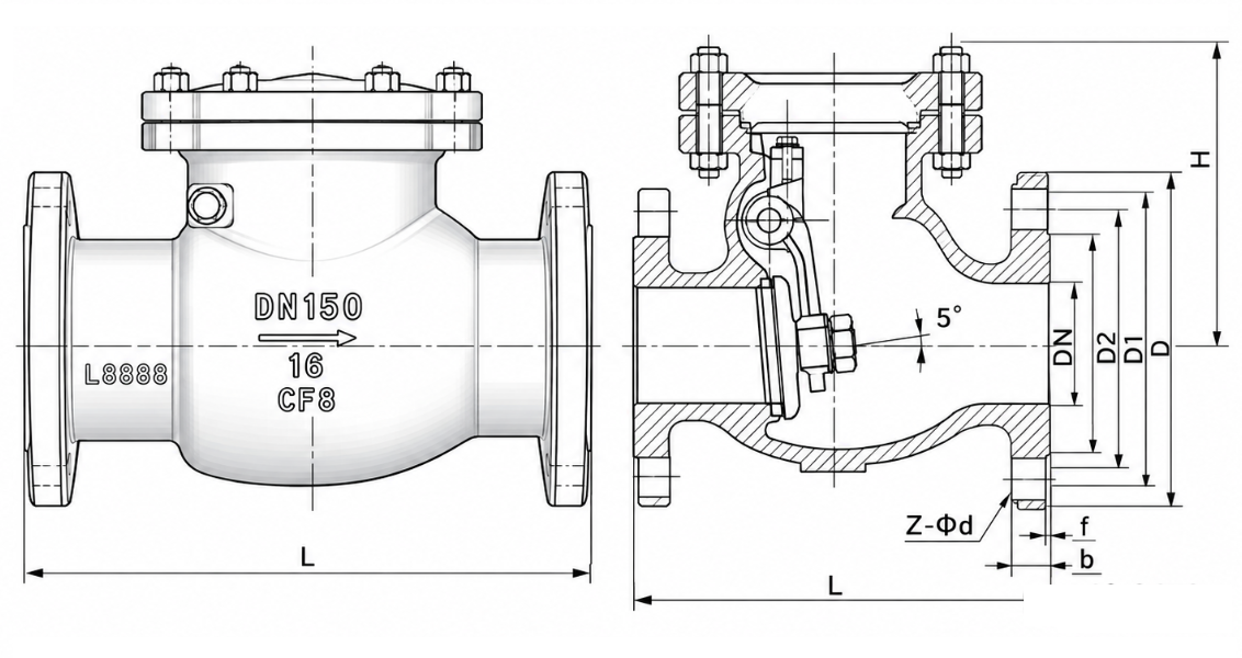
A swing check valve contains a disc suspended from a hinge near the top of the body. Forward flow pushes the disc away from its seat and swings it into the body cavity. As the supporting flow decreases, the disc returns toward the seat. Its movement follows an arc, which is the main visible difference from a guided lift or axial design.
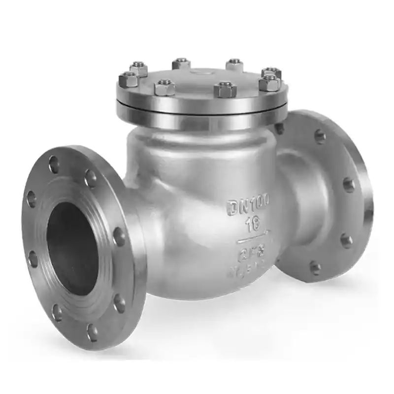
The arrangement can leave a relatively open passage when the disc is sufficiently lifted. This makes swing checks a common starting point for water and general pipeline duties. The body also provides room for a substantial disc and, in many designs, access through a top cover. Hawle's water-line guide illustrates the hinged construction and its use in water systems.
The same disc travel that makes the mechanism easy to understand also affects closing behaviour. A large disc has farther to travel than a short-stroke poppet, and a low operating flow may leave it partly open. A pump that operates at several speeds can therefore expose a swing check to conditions quite different from its original full-flow duty.
A rubber-flapper version uses a resilient flap construction rather than simply duplicating a metal disc and hinge arrangement. It deserves attention when evaluating appropriate water or wastewater duties, but the word “rubber” does not prove that every solid or chemical can pass safely. Passage dimensions and elastomer selection still matter. A conventional swing valve should also not be assumed suitable for downward flow merely because its flanges can be bolted into that position.
A lift check valve opens when forward fluid forces lift a disc or piston clear of its seat. The closure moves within a guide rather than swinging on a hinge. Fluid passes through the seat opening and around the raised element, with a path that depends on the body pattern.
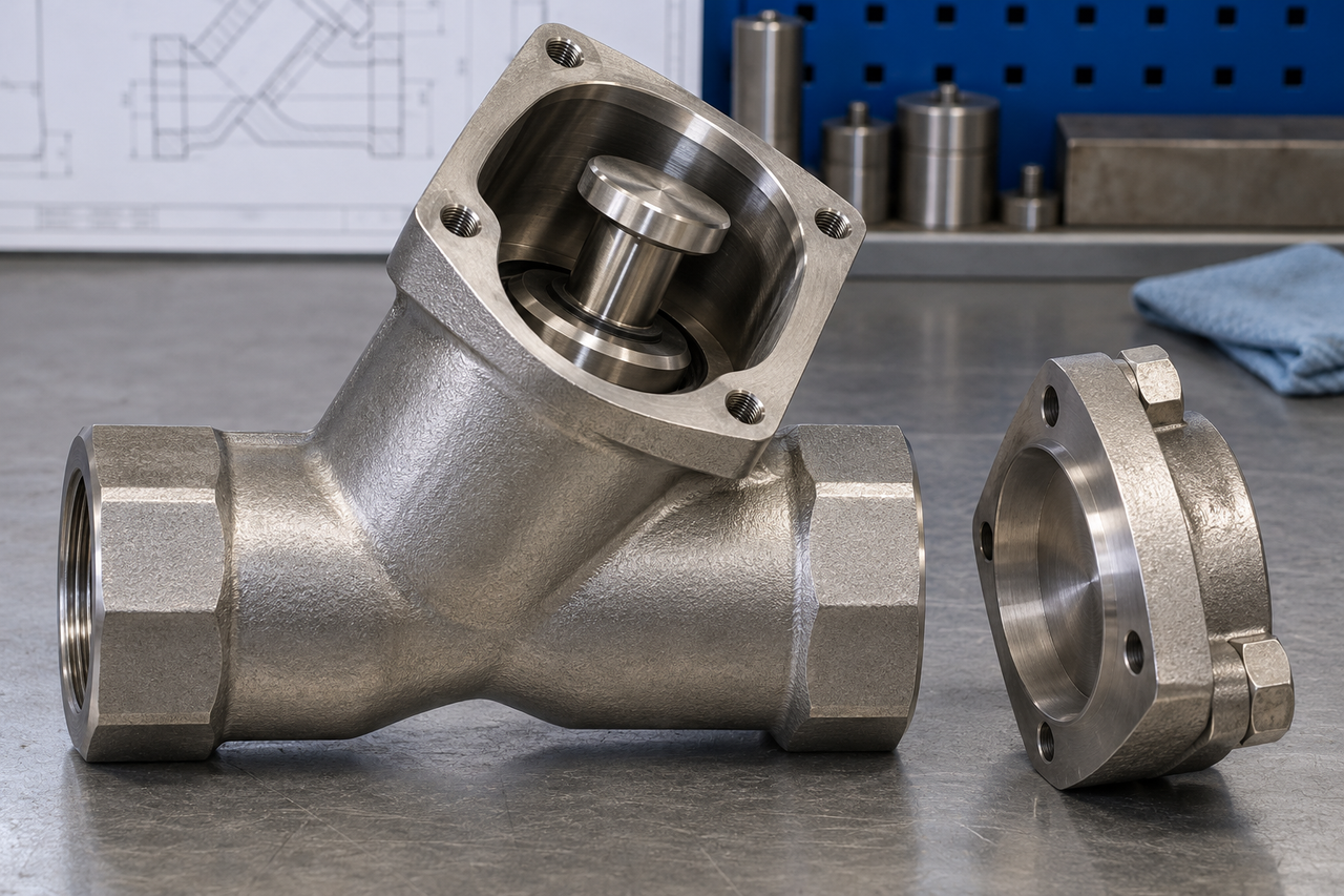
The guided motion is useful where a compact closure and a defined seating path are desirable. However, the guide clearance and passage geometry deserve attention with dirty, depositing or viscous fluids. A design that moves freely with a clean test liquid may behave differently when residue accumulates in a close guiding space.
Y-pattern constructions place the service chamber at an angle to the pipeline. Shinjo's forged steel Y-type check valve identifies a piston disc and bonnet in its parts table. That provides a concrete example of the construction; it does not make every Y-shaped valve identical or transfer one model's rating to the whole family.
Gravity-return lift checks need an installation position that lets the element return as intended. Spring-assisted versions have another source of closing force, but that does not remove every orientation restriction. The approved installation drawing should identify the guide direction and permissible flow direction. For a replacement, matching the existing end connections without understanding that motion is incomplete.
A ball check valve uses a sphere as its closure. Forward flow moves the ball off the seat into a chamber or pocket, and reverse pressure returns it toward the sealing opening. Some small inline designs use a spring; larger water and wastewater designs may use the ball's weight and the body geometry instead.
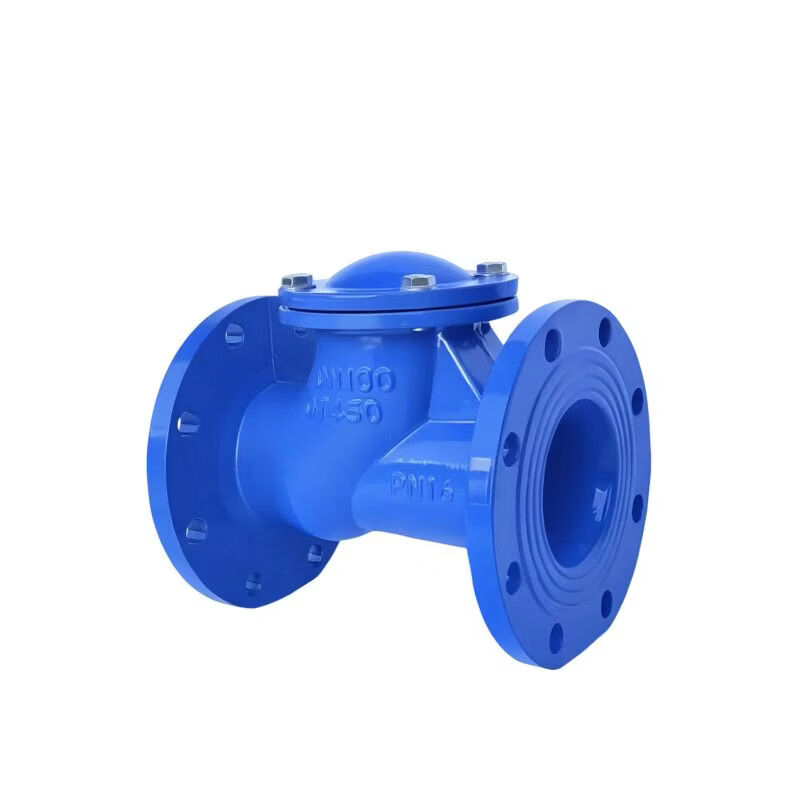
Unlike a quarter-turn ball valve, the sphere does not contain a through-bore that an operator rotates into alignment. It moves out of the flow path and returns to a seat automatically. This distinction is useful when ordering parts: “ball valve” and “ball check valve” describe different mechanisms and are not interchangeable names.
Certain wastewater ball checks provide a smooth passage and a ball selected for the duty. AVK's ball check valve manual is an example of a product-specific installation reference. Solids handling should be judged from the actual passage and permitted installation positions, not from the presence of a ball alone.
The ball's mass, diameter and surface material affect how it moves and seals. A replacement ball that physically fits the chamber may still change the operating behaviour if its weight or coating differs. Rags, stringy material and abrasive particles also present different problems. “Suitable for wastewater” is a starting description, not a complete solids specification.
A dual-plate check valve divides the circular closure into two semicircular plates. They pivot around a central hinge arrangement and commonly use springs to assist return. The plates fold away under forward flow and return toward the seat as the opening forces decline.
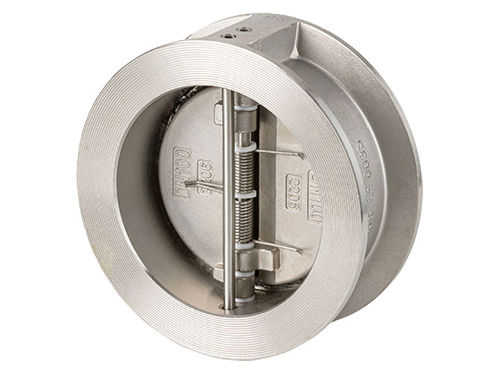
The short body fits between mating flanges in a wafer arrangement. This can save installation length and reduce the weight that has to be handled compared with a large conventional flanged body. CRANE's dual-plate product information describes the compact construction and independently acting springs used in its design.
Compactness introduces installation details that are easy to overlook. Open plates need clearance from adjacent components. The flange bore, gasket position and nearby fittings must not obstruct their travel. A valve can fit the bolt pattern while still having an unsuitable internal clearance arrangement.
“Dual-plate” also does not mean “double check.” Here, two half-discs close one passage within one valve. A double-check assembly places two independently operating checks in series. Choosing a dual-plate model for space reasons does not establish the independent protection or approvals associated with a specified backflow-prevention assembly.
In an axial check valve, the closure moves broadly along the direction of pipeline flow. A guided disc or poppet lifts away from its seat, often against a spring, while the body directs fluid around the central element. Nozzle designs use a shaped internal passage and streamlined parts to manage that flow.
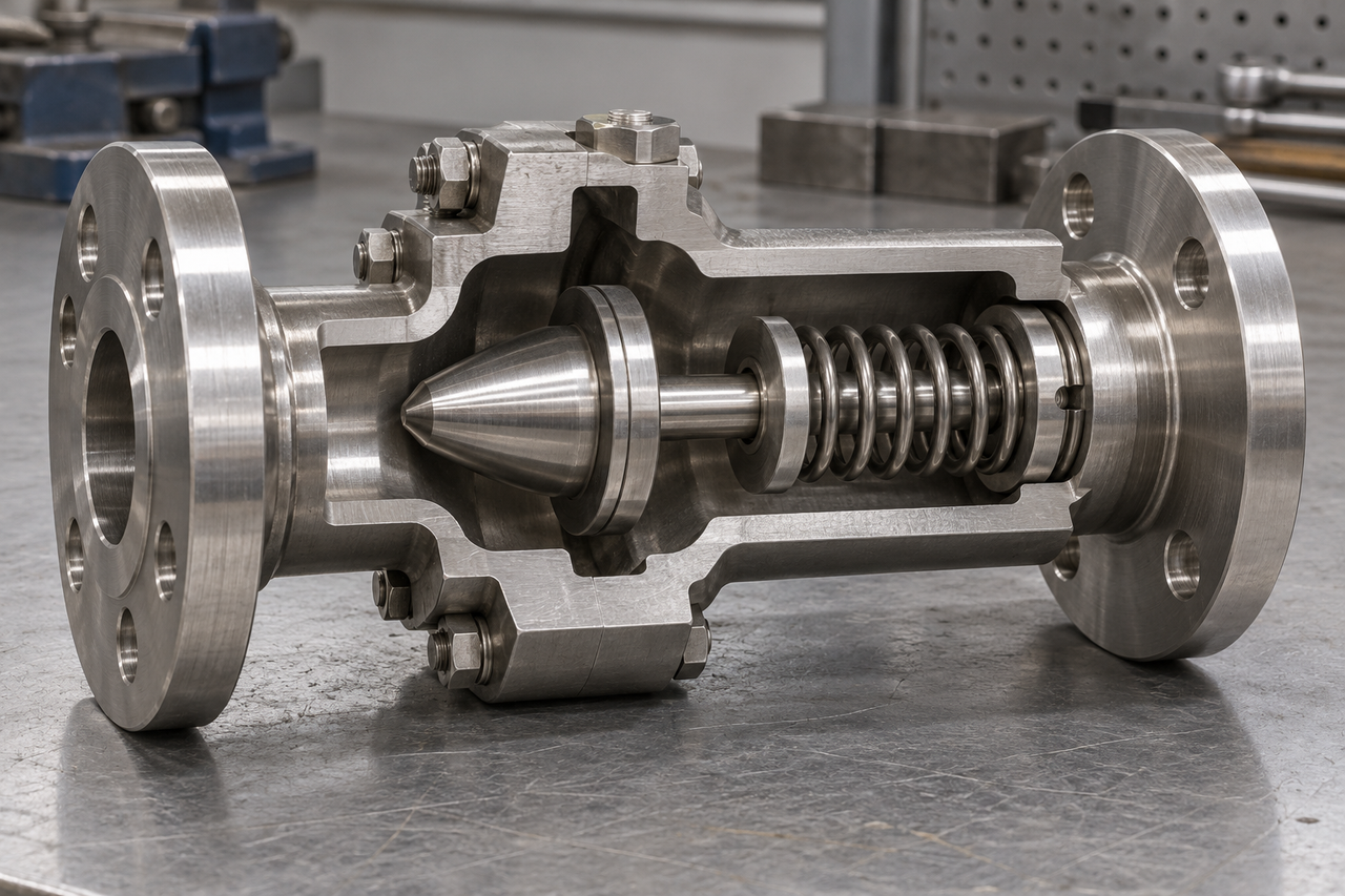
Short travel and spring assistance allow some designs to return toward the seat promptly as forward flow falls. They are often considered where pump shutdown behaviour and valve slam deserve close attention. Val-Matic's silent check valve brochure explains this short-stroke, spring-assisted approach in its clean-water products.
The names do not describe one universally identical construction. Some valves sold as silent checks use a different body form from a streamlined nozzle valve. “Spring-loaded” is broader still: it can describe a small instrument poppet or a dual-plate design. Read the sectional drawing rather than treating these labels as exact synonyms.
There is also a hydraulic trade-off. The central support and closure occupy space in the flow passage, while spring selection influences the opening requirement. A design that responds well at one operating condition may be poorly matched to a branch that normally runs at a fraction of that flow. Compare pressure loss and stable operation across the actual duty range, alongside the required closing response.
A tilting-disc check valve pivots its disc about a shaft positioned differently from the edge hinge of a conventional swing check. The offset pivot changes how fluid forces and disc weight act during opening and closing. The disc tilts within the body rather than swinging from a long upper hinge arm.
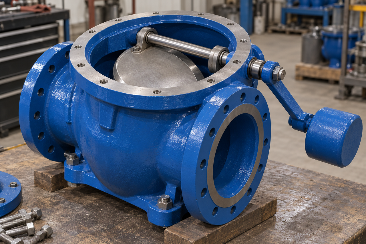
Some versions include an external lever, counterweight or damping cylinder. These features provide ways to influence or monitor motion, but they should not be grouped under a general promise that the valve will eliminate water hammer. The pipeline's deceleration conditions remain part of the problem.
Shinjo's tilting-disc check valve with counterweight arm and cylinder is an example of this arrangement. Its external mechanism also creates a practical space requirement: a lever needs a clear travel envelope, and a damping device needs access for inspection and adjustment.
For larger pumping systems, that access can matter as much as face-to-face length. Placing the valve against a wall may make an otherwise serviceable component difficult to inspect. Selecting the mechanism and planning the installation space should therefore happen together, before the pipe spool arrangement is finalised.
A foot valve combines a non-return function with an intake strainer at the submerged end of a suction pipe. It lets liquid enter while the pump draws from the source, then restricts return flow when the pump stops. Retaining liquid in the suction line can help preserve the conditions needed for the next start.
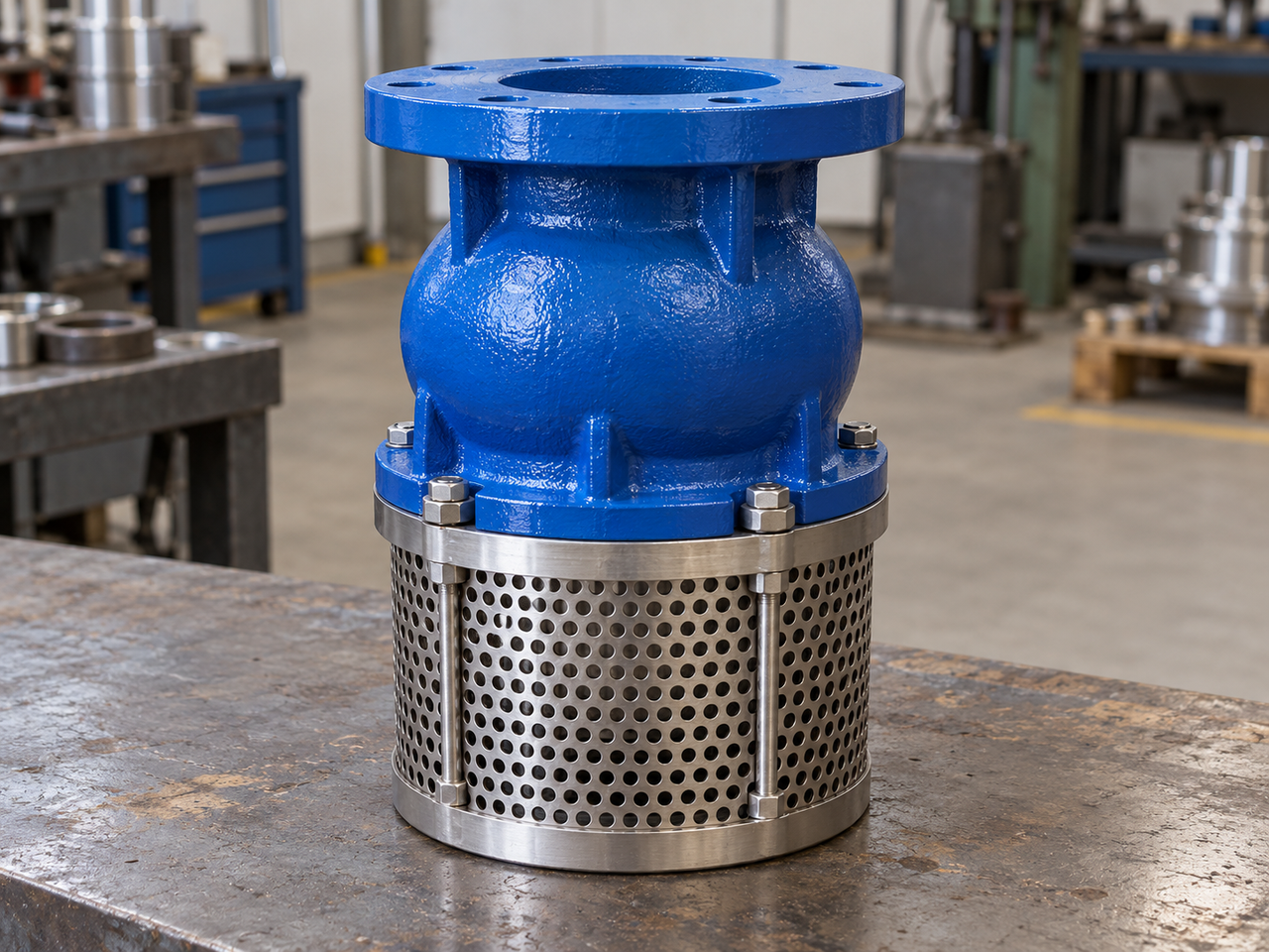
This is an application arrangement rather than a unique closure geometry. The internal checking element can vary. The strainer is the visible feature that distinguishes the assembly from an ordinary inline check, and it introduces another source of suction-side resistance.
A blocked basket reduces the effective inlet area. The pump may then experience a greater suction loss even though the check element itself is intact. Water level, submergence, intake location and debris loading therefore belong in the assessment, along with the valve mechanism. A foot valve cannot correct a suction pipe that admits air through a leaking joint.
Shinjo's ductile iron foot valve with stainless steel mesh shows the combined construction. Use the model's installation instructions to establish position and clearance. A bottom intake should not simply be placed against sediment because the connection happens to point upward.
Flexible designs use an elastomeric element rather than a rigid hinged or sliding closure. In a duckbill valve, forward pressure separates the lips to create an opening. Reverse pressure presses them together. A diaphragm or umbrella-style check uses a different flexible geometry, often at a much smaller scale.
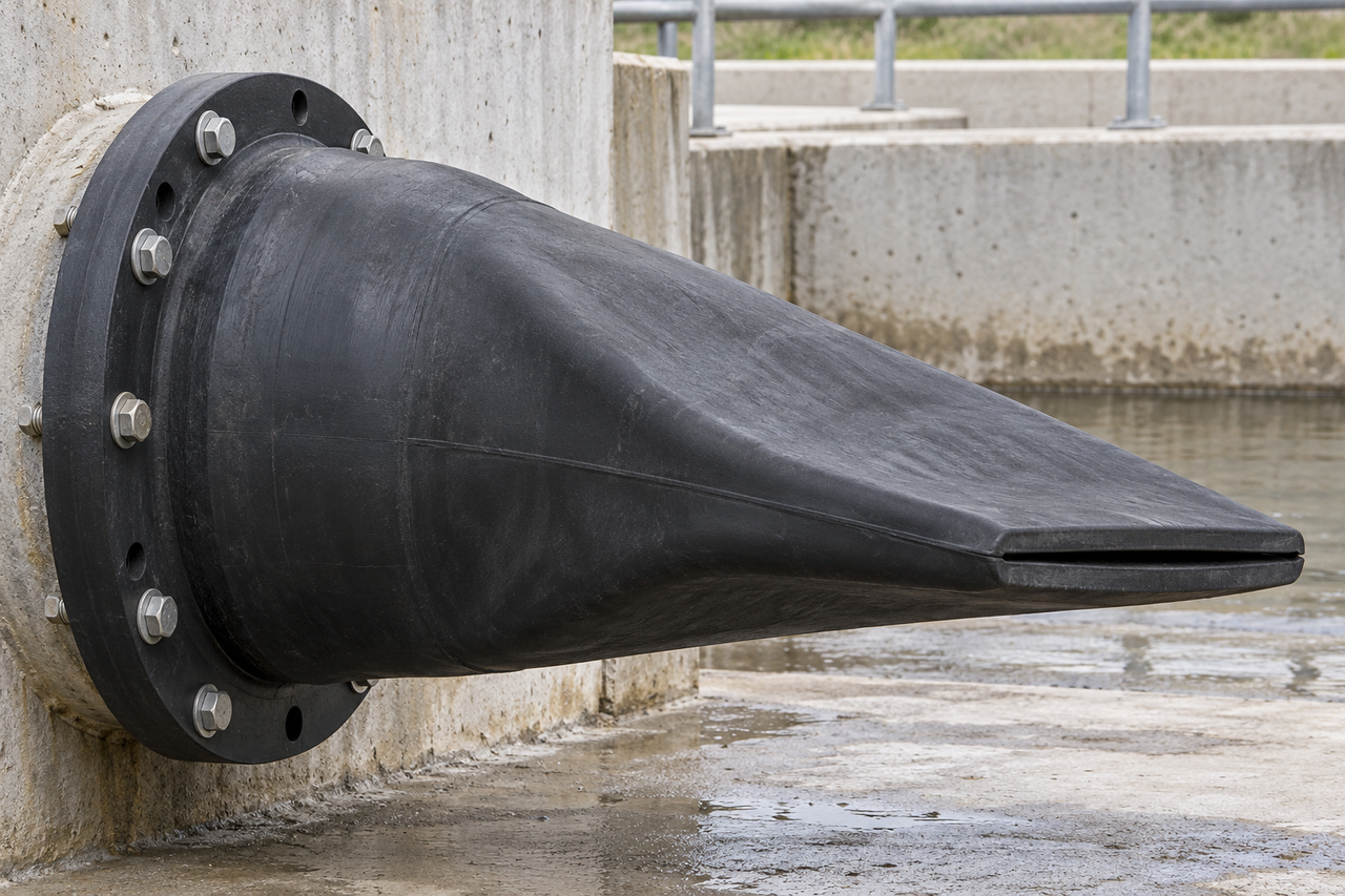
The absence of a metal hinge or sliding piston changes the potential wear and fouling mechanisms. It does not remove the need to select the elastomer, support arrangement and permitted backpressure. Tideflex's product information illustrates reinforced duckbill constructions for backflow duties.
An outlet exposed to debris, sediment or external loading has different constraints from a clean instrument line. Flexible closure travel also changes with the applied pressure and the geometry of the material. Its effective opening is not a fixed hole that can be inferred from the pipe connection alone.
These designs broaden the meaning of “check valve,” but they should not be added to an industrial metal-valve shortlist just to make the type count longer. They are useful alternatives when their operating envelope matches the application. They are also a reminder that a one-way function does not require a conventional metal disc and seat.
Type | Closure movement | Typical reason to consider it | Main point to investigate |
Swing | One disc rotates from an upper hinge | General water and pipeline service | Low-flow disc stability and shutdown response |
Lift/piston | Guided element lifts from a seat | Compact process duties with appropriate fluid conditions | Guide fouling, flow path and installation position |
Ball | Sphere moves into a chamber or pocket | Appropriate water or wastewater duties | Ball material, weight and actual solids passage |
Dual-plate wafer | Two semicircular plates pivot | Short installation length and compact construction | Plate clearance and spring/dynamic behaviour |
Axial/nozzle | Guided closure moves along the pipe axis | Short-stroke response in a suitable pumping duty | Minimum stable flow and pressure loss |
Tilting-disc | Disc rotates about an offset shaft | Larger systems needing a considered motion arrangement | Dynamic assessment and external mechanism clearance |
Foot | Internal closure plus intake strainer | Retaining liquid in a suction line | Suction loss, submergence and strainer blockage |
Flexible/duckbill | Elastomer changes shape | Suitable drainage or specialised low-pressure duties | Elastomer compatibility, head loss and backpressure |
On a pump discharge, the check valve restricts return flow from the downstream system toward the stopped pump. The pressure downstream may come from an elevated reservoir, another running pump, or the stored pressure in the network. The valve's location and response need to suit that arrangement.
In a parallel installation, each branch may experience a different duty as pumps start and stop. A valve selected only for the combined station flow would misrepresent what passes through an individual branch. The important figures are the flows through that valve, including a single pump running at reduced output.
There is a second distinction between keeping reverse flow out of a pump and controlling the whole shutdown transient. A suitable check can address its part of the event, while the network may still need other measures. AVK's selection guide discusses flow characteristics, head loss and non-slam considerations alongside valve type. It does not make those factors interchangeable.
For a long rising main, the shutdown question deserves more than a catalogue label. Pipe profile, pump rundown, water-column behaviour and the valve's dynamic response interact. The valve shortlist can identify plausible mechanisms, but a system assessment determines whether the overall arrangement behaves acceptably.
Process check valves can limit reverse transfer between vessels, branches or equipment. The fluid may be hot, corrosive, viscous or prone to depositing material. Those properties affect both the pressure-containing parts and the moving mechanism.
Chemical compatibility needs to include everything wetted: body, disc or piston, seat, spring, coating, lining and joint materials. A corrosion-resistant shell does not protect an incompatible spring that sits directly in the process stream. Likewise, a lined body does not make every combination of chemical concentration, temperature and pressure acceptable.
For example, Shinjo's H41 lined check valve lists several lining options. Identify which construction suits the fluid: rubber, PTFE, FEP and PFA have different properties. Permeation, abrasion and changes during cleaning can also affect the material choice.
A process diagram may place a check valve next to a manual isolation valve. That pairing is deliberate: automatic reverse-flow restriction and commanded isolation solve different operating needs. If a maintenance task requires the line to be opened, the isolation procedure should not rely on an unverified check seat remaining tight.
In a compressed-air branch, a check valve can restrict return from a receiver or shared header when the local supply pressure falls. Small poppet designs can provide this function without an external control signal. Their cracking differential and flow capacity need to match the available pressure budget.
Air introduces a different interpretation of flow data from a simple water example. A volumetric flow quoted at reference conditions is not the actual volume occupying the line at operating pressure. Catalogue gas-flow curves and their stated conditions are therefore more useful than applying an incompressible liquid relationship without qualification.
The non-return element also does not replace every compressor component. An unloading arrangement, receiver pressure relief and commanded isolation have their own roles. A system that retains pressure downstream of the check may need a deliberate depressurisation path for service. For the broader distinction between air-circuit functions, see Shinjo's pneumatic valve types guide.
In plumbing, a check valve can restrict reverse water movement in a branch or appliance connection. The same general function also appears in building water systems. However, an ordinary single check valve should not automatically be described as an approved device for protecting a public drinking-water supply.
Cross-connection protection is a system requirement. The hazard, type of possible backflow, approved assembly and applicable installation rules determine what is acceptable. Florida's Department of Environmental Protection distinguishes several forms of backflow prevention, including reduced-pressure assemblies, vacuum breakers and double-check assemblies. That distinction is more useful than treating every one-way valve as equivalent.
A double-check valve assembly contains two independently operating checks in series, with the associated shutoffs and test provisions of that assembly. It is different from the two half-discs in a dual-plate wafer check. Two ordinary check valves screwed together also do not establish the approval or performance of a specified assembly.
For a plumbing project, identify the required protection first and then choose an approved product and installation arrangement. Do not start with the cheapest check valve and assume its one-way action meets every cross-connection requirement. The acceptance decision belongs to the applicable authority and the actual assembly approval, not to a general educational article.
A sump pump check valve restricts the water in the discharge pipe from returning to the pit after shutdown. Without an effective check, some of the water just pumped upward can fall back. That returned volume may cause another start sooner than expected, depending on the pit geometry and switch settings.
The size of the effect is easier to see with a simple volume calculation. Assume an internal pipe diameter of 40 mm and a water-filled length of 3 m that could drain back toward the pit. The cylindrical volume is π × 0.040² × 3 ÷ 4 = 0.00377 m³, or approximately 3.77 litres. This is an illustrative inventory calculation, not a prediction of an actual installation's return volume.
The relevant length is the section that can actually drain back, not automatically the entire discharge pipe. The location of the check, pipe profile, outlets and other system features affect what returns. Water below the valve may behave differently from the water it retains above it.
Repeated cycling can also result from incoming water, switch settings, a restricted discharge or other causes. A calculation showing several litres in the pipe does not diagnose the pump by itself. Installation details, including any anti-airlock provisions, must follow the pump and valve manufacturers' instructions. A universal instruction to add or remove a drilled hole would be inappropriate across different pump designs.
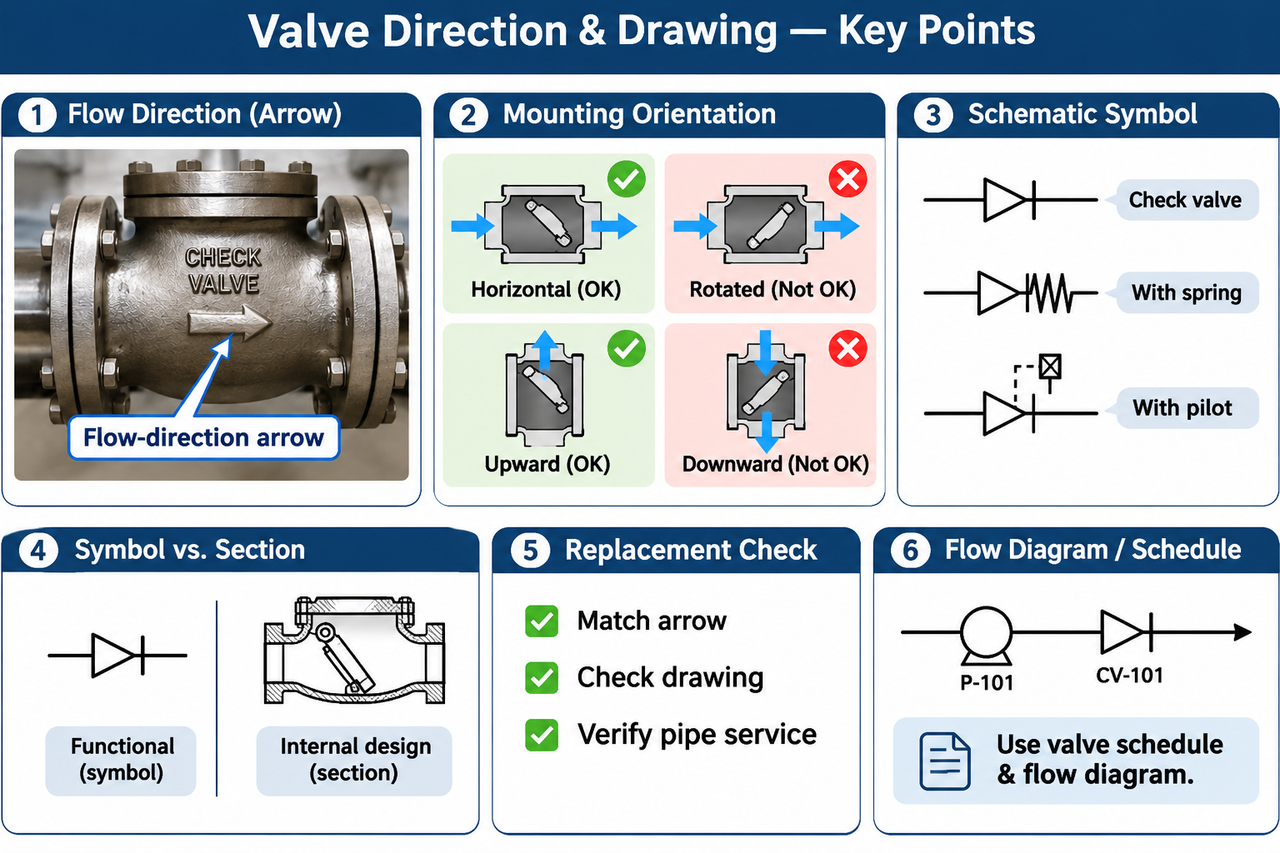
A flow-direction arrow on the body identifies the intended forward flow. That is the direction that should open the check under its permitted operating conditions. It does not, on its own, approve every physical mounting position.
A horizontal pipe with a correctly aligned arrow can still contain a gravity-operated valve rotated into an unsuitable position around the pipe axis. Similarly, vertical upward and vertical downward flow are different cases. The closure may need gravity to help it return, or a hinge may need a particular orientation to move freely.
The check valve symbol on a schematic identifies the one-way function using the drawing convention selected for that document. A spring, pilot or other feature may be represented separately. Read the drawing legend and component designation before inferring a specific internal design from a simplified symbol. The functional symbol and the manufacturer's sectional drawing answer different questions.
When replacing an installed valve, compare the arrow, drawing and actual pipe service. A photograph may reveal where the device sits, but not the normal operating direction or all possible operating modes. A clear valve schedule and flow diagram prevent those assumptions from becoming an incorrect order.

The first description should say what flows through the valve and how that duty changes. “Water” may mean clean cooling water, treated wastewater or a stream carrying solids. “Chemical service” is too broad without the chemical identity, concentration, temperature and relevant cleaning conditions.
Then establish minimum, normal and maximum flow through the individual valve. A check that works at the commissioning test point may spend most of its life at a much smaller flow. Variable-speed pumping, seasonal demand and parallel operation can all change the duty without changing the nominal pipe size.
Give special attention to the minimum sustained operating condition. A closure that cannot remain in a stable position may repeatedly move, strike or vibrate. That is a different problem from a valve whose maximum flow capacity is insufficient. A single catalogue capacity figure cannot answer both questions.
A valve's nominal size tells you how it connects, not whether its internal closure is well matched to the flow. Selecting the largest available bore is not automatically conservative. Larger passages reduce average velocity at a given flow, which can change the forces acting on the closure.
Take 12 m³/h of liquid flow, equivalent to 0.00333 m³/s. Using actual circular internal diameters of 50 mm and 80 mm, the average pipe velocities are about 1.70 m/s and 0.66 m/s respectively. The larger diameter produces roughly 39% of the smaller pipe's average velocity at the same flow.
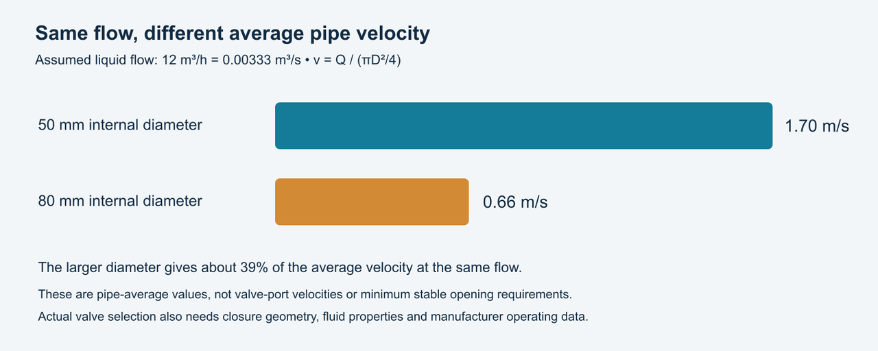
This arithmetic does not prove that either valve will chatter or remain fully open. The local passage area, disc geometry, spring and fluid properties are still unknown. Its value is to show why “larger” changes the operating condition rather than simply adding capacity.
Ask for the manufacturer's pressure-loss information and, where relevant, stable-opening guidance over the expected range. If a smaller valve is considered within a larger line, the reducers, installation arrangement and total system loss must also be assessed. The choice should follow the operating requirement rather than a universal rule to match or reduce one pipe size.
A low cracking differential can be useful when the available driving pressure is small. However, opening at a small differential does not guarantee a small pressure loss at the required flow. Once the closure moves, the available flow area and internal passage determine how the valve behaves.
For incompressible liquid comparisons, manufacturers may supply loss curves, resistance coefficients or Cv/Kv data. Those values need their conditions and units. Cv is a flow coefficient, not a pressure and not a gas-flow unit. A single coefficient should not be stretched across a changing closure position if the manufacturer does not support that use.
Compare losses at the actual duty points rather than comparing two headline coefficients without context. If one valve is partly open at the minimum flow and another is stable, their practical operating differences may matter more than a fully open value. For a gas, use appropriate gas sizing information rather than borrowing a liquid curve.
Maximum allowable service pressure, temperature and differential pressure are related but distinct requirements. The product needs a suitable pressure-temperature envelope for the selected material and construction, as well as an acceptable closure and seat arrangement for the duty.
A PN or Class designation is not a cracking-pressure setting. Nor is a pressure class simply an interchangeable number of psi across all materials and temperatures. Read the applicable rating information for the selected construction. If a pressure surge is credible, its assessment should not be replaced by choosing a higher nominal class without examining the event.
Leakage requirements also need a clear basis. State the fluid, test conditions and acceptance criterion instead of using “leakproof” without qualification. A low-pressure reverse-gas duty and a high-pressure liquid duty may impose different sealing demands even when the body size is identical.
The same distinction applies to temperature. A metal shell may tolerate a temperature that a selected soft seat or spring arrangement does not. The assembly's usable envelope follows its actual component combination, not the most impressive material limit found anywhere in a catalogue.
Suppose a pump branch was originally selected for continuous operation at its normal design flow. Later, a control change makes that pump spend long periods at reduced speed while a second pump handles the peak demand. The pipe connections and maximum pressure have stayed the same, but the check valve now experiences a different flow range.
In that situation, a replacement based solely on the old nameplate misses the reason for the review. Compare the valve's supported operating range with the revised branch flows. If the noise appears only at reduced speed, preserve that observation rather than averaging it into a daily flow figure. If the noise occurs only when the second pump starts, record the sequence and branch conditions. Those two patterns point to different questions even though the same valve is involved.
This is a hypothetical operating scenario, not a reported Shinjo installation. It shows why a good selection record includes operating modes as well as a single design point. When the duty changes, the record provides something concrete to revisit.
If the consequence of a poor shutdown response is significant, obtain the data needed to evaluate it. Dynamic response is not described completely by a static pressure-loss curve. Long pipelines, elevation differences, rapid pump trips and interaction between parallel branches can make that distinction important.
Terms such as non-slam or silent identify a design intention or product characteristic, not a guarantee for every network. A valve may close before substantial reverse velocity in one system and encounter a different flow deceleration in another. A controlled closure device also needs a suitable setting and maintenance condition.
Physical access belongs in this decision. Allow room to remove a cover, withdraw a piston or service a strainer. Keep an external lever's movement clear of walls and pipework. A compact wafer installation needs clearance inside the adjoining pipe as well as space outside it.
These requirements can be recorded in a short selection note: fluid and temperature; minimum, normal and maximum flow; operating and maximum pressure; installation position; permitted pressure loss; leakage criterion; and any shutdown concerns. That is enough to start a useful technical discussion without turning a definition article into a lengthy procurement form.
A useful diagnosis starts with the operating event: steady running, startup, reduced flow or shutdown. Similar noises can have different causes, and a pressure change does not identify a failed component by itself. Record the conditions before deciding that the valve type is wrong.
A valve that appears closed may be installed against the intended direction, have insufficient forward differential, or contain a closure that cannot move freely. A blocked foot-valve strainer adds another possible restriction upstream. The inlet pressure alone cannot separate these possibilities.
Compare the expected flow direction with the body marking and the installation drawing. Then consider both sides of the valve and the operating state of the rest of the system. A closed downstream isolation valve, for example, changes the situation even when the pump discharge gauge shows pressure.
Repeated movement during an otherwise steady duty suggests that the closure is not maintaining a stable position. Possible contributors include a mismatched operating flow, an unsuitable spring, pulsation or disturbed inlet conditions. It should not automatically be treated as the same event as a single shutdown slam.
Swagelok's CH-series service instructions list several different causes of noise and chatter, including sizing and spring-related conditions. Noise alone does not identify the fault. Increasing spring force or changing valve size without identifying the cause may simply move the problem.
A contaminated seat, damaged sealing surface, misalignment or inadequate resealing conditions can allow return leakage. The leakage observation needs a defined direction and pressure condition. Water seen moving elsewhere in the system may have another path, such as a bypass or an interconnected branch.
Seat inspection and internal service require the equipment to be isolated, depressurised and made safe under the applicable procedure. Opening a bonnet is not a way to establish whether a pressurised valve is holding. Once accessible, the evidence may distinguish debris from damaged parts or a material problem.
A sharp shutdown noise can accompany a pressure transient. The important questions are when the event occurs, how rapidly the flow decelerates and how the closure responds. Fitting another valve with the same nominal size and a more reassuring label may not resolve those questions.
A recurring event after a change in pump speed, operating combination or controls deserves a system review. Retain the operating sequence and pressure observations as evidence. They provide a better starting point than assuming the seat impact alone explains the entire event.
Observed pattern | Useful distinction | Evidence that helps |
Little or no forward delivery | Opening problem versus another system restriction | Direction, pressures on both sides, operating sequence |
Repeated chatter at reduced flow | Steady instability versus shutdown transient | Actual flow range and whether the duty is pulsating |
Sustained return after shutdown | Seat leakage versus another return path | Valve reseal conditions and piping arrangement |
Single sharp shutdown event | Closure behaviour versus broader surge sources | Pump rundown and time-related pressure observations |
Loss of prime in suction service | Check leakage versus air entering elsewhere | Suction layout, joints and retained liquid behaviour |
A second check adds another closure, but the arrangement also adds resistance and can create a trapped section between the valves. If both units encounter the same debris or unsuitable operating conditions, duplication does not remove that common cause. Start by identifying the leakage mechanism and the required system function. An engineered series arrangement and an approved double-check assembly are different decisions.
Yes. The non-return function can retain pressure on one side after another part of the system has been depressurised. The pressure boundary depends on the complete piping arrangement, including other closed valves. A zero reading at one gauge therefore does not establish that every connected section is depressurised. The service procedure needs to identify the relevant trapped sections and the means of safely releasing their stored pressure.
A stop-check valve combines automatic non-return action with a means of forcing or holding the closure shut. That additional function distinguishes it from an ordinary automatic check. It is a specific construction, not a name for every check valve installed next to a manual shutoff. Its operation and permitted use follow the selected product's documentation.
There is no useful universal replacement interval for all check valves. Fluid condition, cycles, materials, operating stability and the consequences of failure differ too much. Use the manufacturer's maintenance guidance and the site's inspection evidence. A valve repeatedly damaged by the same operating problem needs that cause addressed as well as replacement parts.
Choose a check valve by the movement it must perform in the actual system. A general pipeline duty may lead you toward a swing construction; a short installation space may favour a wafer arrangement; a sensitive pump shutdown may require a closer look at a short-stroke or controlled-motion design. Suction retention introduces the separate requirements of a foot valve and its strainer.
The decisive information is the fluid, flow range, pressure and temperature, permitted orientation, sealing requirement and shutdown behaviour. With those conditions defined, Shinjo's check valve range provides a starting point for comparing specific constructions. Confirm the selected model against its drawing and operating data before making it part of the piping design.
