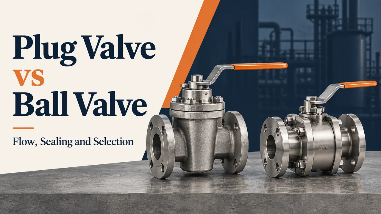
The main difference between a plug valve and a ball valve is the closure and sealing arrangement. A plug valve rotates a ported cylindrical, tapered or eccentric plug. A ball valve rotates a bored sphere or a shaped ball segment. Both commonly provide quarter-turn shutoff, but they differ in the way they carry pressure loads, contact their seats and accommodate flow.
For many clean-fluid isolation duties, a full-bore ball valve is a practical starting candidate because it offers a large passage and familiar automation options. A plug valve is worth comparing when a lubricated sealing system, compatible sleeve or eccentric seating motion addresses the actual medium. Those advantages belong to specific constructions; choosing the family name alone is insufficient.
This comparison follows the questions buyers usually ask: Which valve loses less pressure? Which seals better? Which is easier to operate and maintain? What changes for gas, sludge or chemicals? And which costs less once the actuator, installation and service work are included? The focus is industrial isolation, with control designs identified separately.
A plug valve opens or closes a flow path by rotating a plug inside the body. In a conventional two-way design, a passage through the plug aligns with the inlet and outlet when open. A quarter turn presents the solid part of the plug across that path to close the valve. The passage can be round or rectangular; the plug can be cylindrical or tapered.
The body contains process pressure. The stem connects the plug to a lever, gearbox or actuator, while the sealing interface limits leakage across the closed valve. A conventional lubricated design uses a specified sealant system at the plug-to-body interface. A non-lubricated sleeved design places a non-metallic sleeve between those parts. An eccentric design changes the plug's approach to its seat rather than simply increasing the contact area.
These variations explain why plug valves appear in different duties. A sealant-assisted pressure-balanced valve used for gas isolation and an eccentric valve considered for sludge are different engineering choices. Neither should be treated as the universal plug valve against which every ball valve is compared.
Shinjo's plug valve guide introduces the broader family. Here, the important point is that the plug shape, port and sealing arrangement work together. The advantages and limitations become clear only when that complete construction is compared with a specific ball-valve design.
A ball valve uses a sphere with a bore to connect or interrupt the flow path. With the bore aligned to the pipe, fluid passes through the open valve. Rotating a conventional two-way ball through 90 degrees brings its solid surface across the passage. Seats around the ball provide the shutoff interface, and a stem connects it to the operator.
A full-bore construction retains a large opening through the valve; a reduced-bore construction has a smaller passage. These labels describe flow geometry. Floating and trunnion-mounted describe how the ball is supported, while one-, two- and three-piece or top-entry describe aspects of body construction and access. They answer different questions and can overlap in one valve.
For example, a ball valve can be trunnion-mounted, full-bore and three-piece at the same time. A V-port ball valve changes the opening for control duty. It should not be confused with an ordinary isolation valve simply because both contain a ball.
The ball and seats are process-contact parts, so the body alloy alone does not establish chemical compatibility. Stem packing also has a separate job: it limits leakage to the environment rather than leakage through the closed seat. This distinction applies to plug valves too and matters when comparing what a supplier means by tight shutoff.
The table below gives the comparison at a glance. The sections that follow explain the mechanism behind each difference and where the usual generalization stops being useful.
Buyer concern | Plug valve | Ball valve | What decides the comparison? |
Design and load path | Ported plug; conventional contact, sleeve or eccentric seat approach | Bored ball; floating or mechanically supported construction | Closure support and seat design |
Flow and pressure drop | Round or rectangular ports; capacity varies by construction | Full, reduced or shaped bore; full-bore often attractive for low-loss isolation | Size-specific Cv/Kv and usable passage |
Sealing and leakage | Sealant, sleeve or engineered seat interface | Soft or metal seats with different loading arrangements | Specified shutoff test and material system |
Pressure and temperature | High-pressure designs exist; sleeve/sealant can limit the envelope | Broad industrial range; seat/seal limits still apply | Complete assembly rating, not family name |
Torque and automation | Contact pattern can increase effort; balancing/eccentricity can reduce its effect | Support and seat loading influence effort; often convenient for automated isolation | Duty-specific torque and actuator output |
Flow regulation | Requires an engineered control construction | Requires V-port, segmented or other control construction | Trim characteristic and installed duty |
Maintenance | Sealant work or seat-system service; access depends on body design | Seat/packing service; three-piece and top-entry can provide repair routes | Actual disassembly route and shutdown space |
Wear and service life | Depends on seating contact, deposits, abrasion and compatibility | Depends on seats, supports, deposits, abrasion and compatibility | Relevant service evidence, not a fixed lifespan |
Size, weight and replacement | Body/operator dimensions vary with the construction | Compact options exist; industrial assemblies can still be substantial | Offered drawing, mass and installation envelope |
Cost | Sealing system and operator affect purchase and service cost | Bore, support, seats and actuator affect purchase and service cost | Equivalent supplied and installed scope |
The visibly different closure members produce different internal load paths. A conventional plug may contact a sleeve or body interface over a substantial part of its movement. A ball closes against seats surrounding the bore; whether the seats also support the pressure-loaded ball depends on the construction. This difference helps explain operating effort and wear, but it does not establish a universal performance ranking.
Both valves can be operated manually or with electric, pneumatic or other appropriate actuators. Quarter-turn describes travel, not required torque, closing time or failure action. An externally compact valve can contain a highly loaded sealing interface, while a larger supported construction can distribute those loads differently.
A sectional drawing is more useful here than the handle shape. Trace the fluid through the open passage, then trace the mechanical load from the operator through the stem to the closure and its supports. The first path explains capacity and retained-fluid spaces. The second shows where friction and pressure loading influence operation.
Ball support is an important design difference within the comparison:
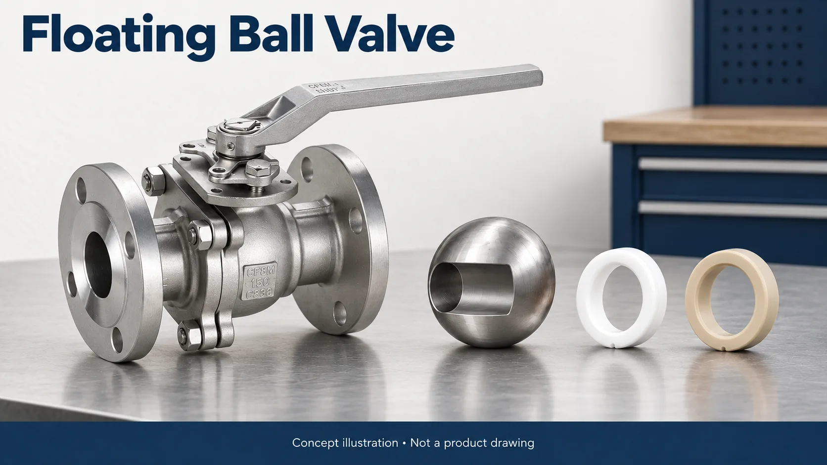
In a floating construction, the ball can move slightly under pressure loading. In a common arrangement, upstream pressure pushes it toward the downstream seat, helping form the closed seal. The seats therefore play a role in both sealing and supporting the pressure-loaded ball.
Compared with a conventional plug interface, a floating ball transfers its shutoff loading through the ball-seat arrangement. It is familiar in many isolation duties, but increasing size or differential pressure changes both loading and operating effort.
Soft-seat compatibility, available flow capacity and the torque under the intended operating conditions matter more than the general claim that ball valves are easy to turn. Shinjo's ball valve range includes floating designs alongside other constructions.
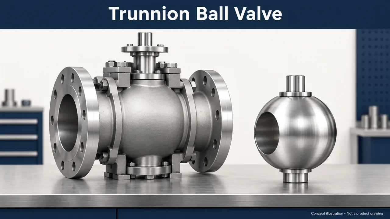
A trunnion-mounted construction supports the ball mechanically rather than relying on the seats in the same way as a floating design. The seat arrangement supplies the required contact with the supported ball. This changes how pressure loading is managed and makes the design relevant to demanding isolation applications.
Seat behavior remains configuration-specific. A valve described as trunnion-mounted does not automatically provide every isolation or cavity-relief arrangement. The seat design, permitted pressure direction and bleed function need to match the process objective.
Shinjo lists a three-piece trunnion-mounted ball valve. Its product-family label is a route to a specific offer, not a substitute for the offered assembly's drawings and testing requirements.
Design question | Conventional plug construction | Floating ball | Trunnion-mounted ball |
What moves against the seal? | Plug relative to sleeve/body/seat system | Ball relative to seats, with slight pressure-driven displacement in common designs | Supported ball rotates against a configured seat system |
What changes under pressure? | Plug loading and contact depend on balancing and geometry | Seat loading includes the pressure-loaded ball | Ball supports and seat arrangement manage the load differently |
Why does it matter? | Influences effort and sealing-system requirements | Influences torque and seat selection as duty increases | Provides another construction to evaluate for demanding isolation |
The handle reaching its stop confirms travel only. It does not measure seat leakage. That is why operating completion and shutoff acceptance remain separate checks for either valve family.
A full-bore ball valve is often a strong candidate where open-valve pressure loss matters. A plug valve can also offer suitable capacity, so the decisive comparison is the actual port and published Cv/Kv, rather than the shape of the closure alone.
A full-bore ball valve presents a passage intended to retain a large flow area through the open valve. A reduced-bore ball valve introduces a smaller opening. Plug valve ports also vary, including round and rectangular arrangements. Consequently, nominal pipe size is not enough to rank their flow resistance.
Cv or Kv provides a defined way to describe flow capacity. For two valves being compared under the same fluid and flow conditions, capacity data helps establish the pressure loss rather than relying on closure shape. The port dimensions and geometry explain why that capacity differs.
The practical consequence appears in a line where pressure loss matters. A smaller internal passage can consume pressure that the downstream equipment needs. Increasing nominal valve size might restore capacity, but can also change connection details, weight, installation space and cost. The comparison should therefore start with the required flow and available pressure, then examine the offered valve's actual passage.
A rectangular port is not automatically unsuitable, and a round bore is not automatically full-bore. Where pigging is required, the complete passage and valve construction need explicit approval for that duty; a large opening alone does not establish piggability.
A worked flow-capacity comparison. Consider two hypothetical, fully open isolation valves carrying clean water at a constant 100 US gallons per minute. Suppose Valve A has a published Cv of 100 and Valve B has a Cv of 160. These values are illustrative inputs, not data for a Shinjo plug or ball valve.
For a simplified, non-choked liquid calculation with specific gravity SG, the relationship is:
Pressure drop in psi = SG × (flow in US gpm ÷ Cv)².
At SG = 1, Valve A gives (100 ÷ 100)² = 1.00 psi, while Valve B gives (100 ÷ 160)² = 0.391 psi. The difference is about 0.609 psi at that flow. Keeping the flow and fluid constant allows the effect of the capacity difference to be seen without changing several variables at once.
Illustrative water flow | Valve A, Cv 100 | Valve B, Cv 160 |
50 US gpm | 0.250 psi | 0.098 psi |
100 US gpm | 1.000 psi | 0.391 psi |
150 US gpm | 2.250 psi | 0.879 psi |
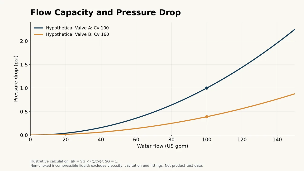
Calculated from the stated hypothetical Cv values at SG = 1; these curves are not measured plug- or ball-valve performance.
The table shows why a capacity difference becomes more consequential as flow increases under these assumptions. It does not establish a measured advantage for either valve family. A plug valve with the higher applicable Cv would take the lower-loss role just as a ball valve would.
This equation is a screening illustration. It assumes a suitable incompressible liquid case and does not model cavitation, choking, viscosity effects or adjoining fittings. Gas and steam need their own applicable sizing methods. Emerson's Control Valve Handbook provides the engineering context for capacity and sizing. For an actual installation, the manufacturer's data and the complete system conditions govern the calculation.
A published maximum Cv should also describe the relevant opening and construction. Comparing one valve's full-open capacity with another valve's control trim at a different position would confuse the result. The same applies to mixing Cv and Kv numbers without converting units: they are related flow coefficients, but their numerical values are not interchangeable.
The engineering decision is what to do with the pressure-loss difference. A line with ample available pressure may gain little from a larger passage, while a pressure-constrained transfer line may value it. The lower loss must be considered alongside the chosen sealing system and installation constraints. Capacity is one part of the choice, not permission to ignore a material or isolation requirement.
Flow-related requirement | Plug valve comparison | Ball valve comparison |
Low full-open loss | Evaluate port area and actual capacity | Compare full-bore and reduced-bore capacity at the same size |
Large particles or pig passage | Obtain the allowed passage and construction-specific approval | A full-bore label is a starting point; confirm actual passage and approval |
Flow control | Evaluate a control plug design | Evaluate a control ball design rather than an ordinary shutoff bore |
Neither family is automatically tighter. Plug valves offer several sealing routes, including sealant-assisted contact and sleeves; ball valves offer soft- or metal-seat systems. Their leakage performance must be compared under the same specified conditions.
A comparison of sealing surfaces should explain the mechanism, then connect it to a defined shutoff requirement. More contact area does not, by itself, establish lower leakage. Surface condition, seat loading, sealing material, differential pressure and the test conditions all influence the result.
For a lubricated plug valve, the sealant must retain its intended function in contact with the medium. A sleeved valve transfers much of that compatibility question to the sleeve. A soft-seated ball valve likewise depends on the seat material and supporting construction. A metal-seated option changes the material and contact system, but does not create an unlimited temperature or abrasion rating.
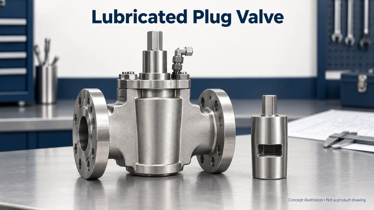
A lubricated plug valve uses an approved sealant or lubricant at the plug-to-body interface. An engineered distribution arrangement delivers it to the relevant surfaces, supporting sealing and operation. The sealant is part of the valve's service requirements, not an interchangeable consumable chosen only by availability.
Pressure-balanced constructions address the way process pressure loads the plug. Their purpose is to manage forces that influence operation, but the resulting torque must still be established for the offered valve and duty. Flowserve's Dynamic Balance steel plug valves document pressure balancing and sealant distribution in a series that includes high-pressure designs. This is a useful example of why plug valves should not be described as a low-pressure-only family.
Compared with a ball-seat construction that does not require this treatment, the lubricated plug brings a process-contact consumable and a recurring service task. The plant must accept both. Shinjo's pressure-balanced plug valve is one candidate to evaluate with those conditions in mind.
Sealant selection has two different questions behind it. Can the sealant continue to perform at the interface, and can the process accept any contact with it? A material that resists the fluid may still be unacceptable where downstream processing excludes that substance. Conversely, an accepted substance may not retain its function at the service temperature. The valve and sealant should be treated as a specified pair.
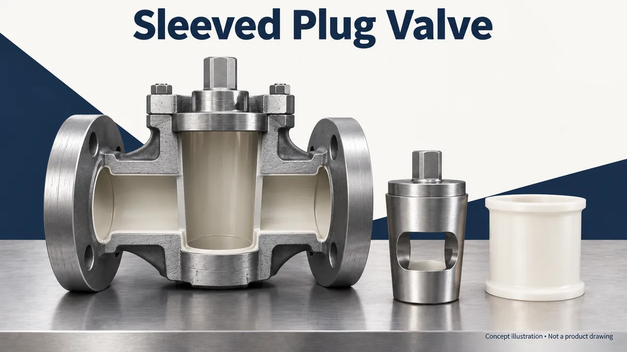
In a sleeved plug valve, a non-metallic sleeve sits between the plug and body. The sleeve forms the sealing interface and reduces direct metal contact. This construction avoids routine sealant injection at that interface, making it relevant when sealant contact is undesirable or access for replenishment is difficult.
Its limitations move the selection toward the sleeve. Temperature, pressure, chemical exposure and cycling must remain within the offered construction's limits. Cleaning fluids and temperature excursions belong in that assessment, even if normal production conditions appear straightforward.
Shinjo's non-lubricated sleeved plug valve identifies a PTFE sleeve. That identifies a material to evaluate; it does not establish suitability for every chemical or guarantee that the complete assembly needs no maintenance. Stem seals, operators and the sleeve itself still require an appropriate service plan.
Gas service makes leakage requirements particularly important, but it does not justify a universal sealing winner. Seat leakage and external stem leakage remain separate questions. Any stated performance needs an applicable test basis for the offered design, with the medium, pressure and acceptance criteria identified.
Isolation terminology adds a second question beyond ordinary seat leakage: which pressure boundaries must remain isolated, and where can trapped pressure be observed or relieved? A bleed connection is a physical feature. The required isolation behavior depends on the seat arrangement and the pressures applied to it. For a project-specific DBB or DIB requirement, the drawing and stated test arrangement should make that behavior explicit.
A useful review follows the pressure paths. Identify the upstream line, downstream line and body cavity or intervening space. Describe which one can be pressurized in each relevant condition, then identify the intended sealing and relief response. This is more informative than asking for every isolation acronym on the same quotation.
Sealing question | Plug valve | Ball valve |
Which parts form shutoff? | Plug with sealant, sleeve or engineered seat | Ball with the selected soft or metal seat arrangement |
Is a process-contact consumable involved? | In a lubricated construction, the specified sealant system is part of selection | Routine plug-type sealant injection is not a defining feature; any offered injection system is configuration-specific |
What can leak independently? | Closed seat and stem/body boundaries | Closed seat and stem/body boundaries |
What demonstrates suitability? | Test basis, materials and applicable operating conditions | The same evidence under comparable conditions |
Ball valves are widely used across demanding industrial duties, but plug valves are not confined to low-pressure service. The body rating and the limits of seats, sleeve, seals or sealant together determine the usable envelope.
Pressure-temperature limits belong to the complete assembly. The body might tolerate conditions that a seat, O-ring, sleeve or sealant cannot. Cleaning cycles can also expose the internals to a different chemical or temperature envelope from ordinary production. These conditions should be described together rather than assigned to separate purchasing teams without reconciliation.
Body cavities introduce another construction-specific issue. Fluid retained within a cavity can require a defined pressure-management arrangement. SLB's Grove B5 ball valve includes body relief for pressure arising from liquid thermal expansion. That is a documented feature of that product, not proof that every ball valve provides the same protection or that all plug valves are free of retained-fluid concerns.
For a plug valve, a polymer sleeve can become the limiting part even when the metal body has ample pressure capacity. A lubricated design instead brings the specified sealant's temperature and process acceptance into the review. Those are distinct limitations, so a statement about one plug construction should not be applied to all the others.
For a ball valve, a soft seat may provide the required shutoff within its intended envelope, while a metal-seated construction addresses a different contact and material system. Changing from soft to metal seats can change leakage acceptance, friction and required operation as well as temperature capability. It is not simply an upgrade with no other consequence.
Chemical compatibility follows the complete wetted system for both families. A stainless steel body does not prove that a PTFE sleeve, another polymer seat, elastomer seal, packing or process-contact sealant is acceptable. Concentration, temperature, contaminants and cleaning exposure can make a familiar material behave differently.
A useful pressure-temperature comparison therefore starts with two actual assemblies. Compare them at the operating temperature, include startup and cleaning excursions, and distinguish line pressure from the differential pressure against which the closure must operate. A catalogue family with a higher maximum rating may offer no benefit if its quoted seat system does not suit the medium.
Constraint | Plug valve: likely focus | Ball valve: likely focus |
High pressure | Body class, plug loading/balancing and sealing system | Body class, floating/trunnion support and seat configuration |
Elevated or changing temperature | Sleeve, sealant and seals as well as the body | Seats, seals and packing as well as the body |
Corrosive medium | Every wetted part and any accepted sealant | Every wetted part, including seats and seals |
Liquid retained in a closed assembly | Offered retained-pressure behavior | Offered cavity-pressure and relief behavior |
Conventional broad-contact plug designs can require more operating effort than a comparable ball design. That is a useful starting observation, not an actuator-sizing rule: pressure-balanced and eccentric plugs, and floating versus trunnion balls, change the comparison.
Torque is the rotational effort needed to move the closure member. The requirement can differ when the valve first breaks away, while it travels and as it reaches the closing position. Pressure loading, friction, packing and the state of the medium can influence the result.
Some plug constructions have substantial contact over their movement, while balancing or eccentric operation changes the loading or contact pattern. Floating and trunnion-mounted ball constructions also manage loads differently. Family-level claims such as “plug valves always need more torque” hide these differences.
There are clear exceptions even within smaller valve ranges. The Swagelok P4T and P6T catalogue describes low-torque instrument plug valves. Those valves are not substitutes for large industrial plug valves; they demonstrate why the scope of a torque claim must be stated.
An automated offer should connect the valve's torque requirement to actuator output at the available supply conditions. Maximum operating differential pressure matters, as do the required failure action and the way actuator output varies through travel. A valve that turns freely without process pressure has not demonstrated its installed operating requirement.
Manual operation has similar consequences. A lever needs room to move and an acceptable operating effort. A gearbox changes the effort and operating time but also adds space and maintenance needs. The valve, operator and installation should be evaluated as one arrangement.
An actuator comparison should cover the whole movement. A supplier may quote a maximum valve torque, but the relevant values at breakaway, running and seating can differ. Pneumatic actuator output can also change with travel and with the available supply pressure. Matching two headline numbers without their conditions can overlook the point at which the assembly has the least operating margin.
Long idle periods add another operating case. The duty may be to move a valve after months in one position, rather than to repeat the movement immediately after a factory stroke test. Deposits and service exposure are reasons to establish the manufacturer's applicable sizing basis, not to invent a universal multiplier. The necessary allowance belongs in the supplier's documented selection.
Failure action should be stated separately from normal operation. A spring-return arrangement needs to deliver the required movement under the applicable process load; a double-acting arrangement requires a defined accessory scheme if a particular response to supply loss is expected. “Pneumatic” alone describes the power source, not the assembly's failure behavior.
Operating speed creates a further trade-off. A quarter-turn mechanism can move quickly, but the piping system may require a controlled closing time. Rapid closure is not automatically an advantage in a liquid line where the system response matters. The chosen actuator and accessories should serve the process's timing requirement rather than maximize speed because the valve permits it.
Operating concern | Plug valve | Ball valve |
Source of effort | Plug contact, pressure loading, packing and medium condition | Seat friction, pressure loading/support, packing and medium condition |
Design route to investigate | Balancing, appropriate sealing system or eccentric movement | Appropriate floating/trunnion support and seat design |
Manual installation | Lever/gearbox effort and clearance | Lever/gearbox effort and clearance |
Automated installation | Applicable valve torque through travel and actuator output | The same comparison at actual supply and process conditions |
Ordinary isolation plug and ball valves should not be compared as if either automatically provides good continuous control. Engineered eccentric plugs and V-port or segmented-ball designs are the relevant alternatives when the process needs modulation.
Flow regulation adds another distinction. An inherent characteristic describes how capacity changes with travel under defined conditions. Installed behavior also reflects the surrounding system. Neither a linear nor an equal-percentage characteristic follows automatically from the words “ball” or “plug.” Emerson's Fisher valve catalogue describes an equal-percentage characteristic for its V-notch segmented-ball designs, illustrating that construction matters.
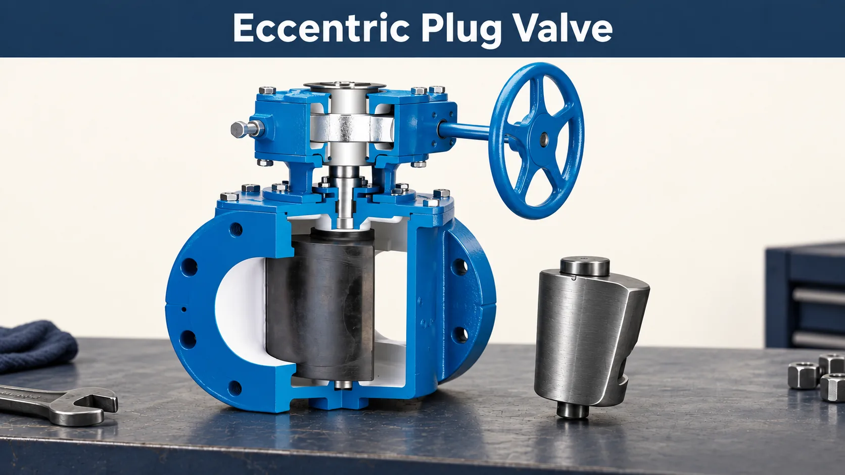
An eccentric plug follows an offset path as it rotates. In an engineered eccentric control construction, the plug approaches its seat near closure rather than rubbing against it throughout the entire movement. Changing the contact pattern can be useful in services where deposits, erosion or seating wear complicate operation.
Emerson's eccentric plug valve explanation describes this movement and identifies both throttling and on-off applications in its control-valve range. That evidence supports the mechanism and the existence of modulating designs; it does not prove that every eccentric isolation valve has the same control performance.
For wastewater or solids-bearing service, Shinjo's eccentric plug valve provides a product starting point. The actual particle conditions, seat selection and operating duty still distinguish a suitable installation from an unsuitable one.
For an eccentric valve, flow direction and installation instructions form part of the operating design. The seat location and approach motion shown in a drawing help explain why a manufacturer might prescribe a particular orientation for a specific duty. A generic photograph cannot settle that requirement. This matters especially when the valve must close against accumulated solids or operate at a substantial differential pressure.
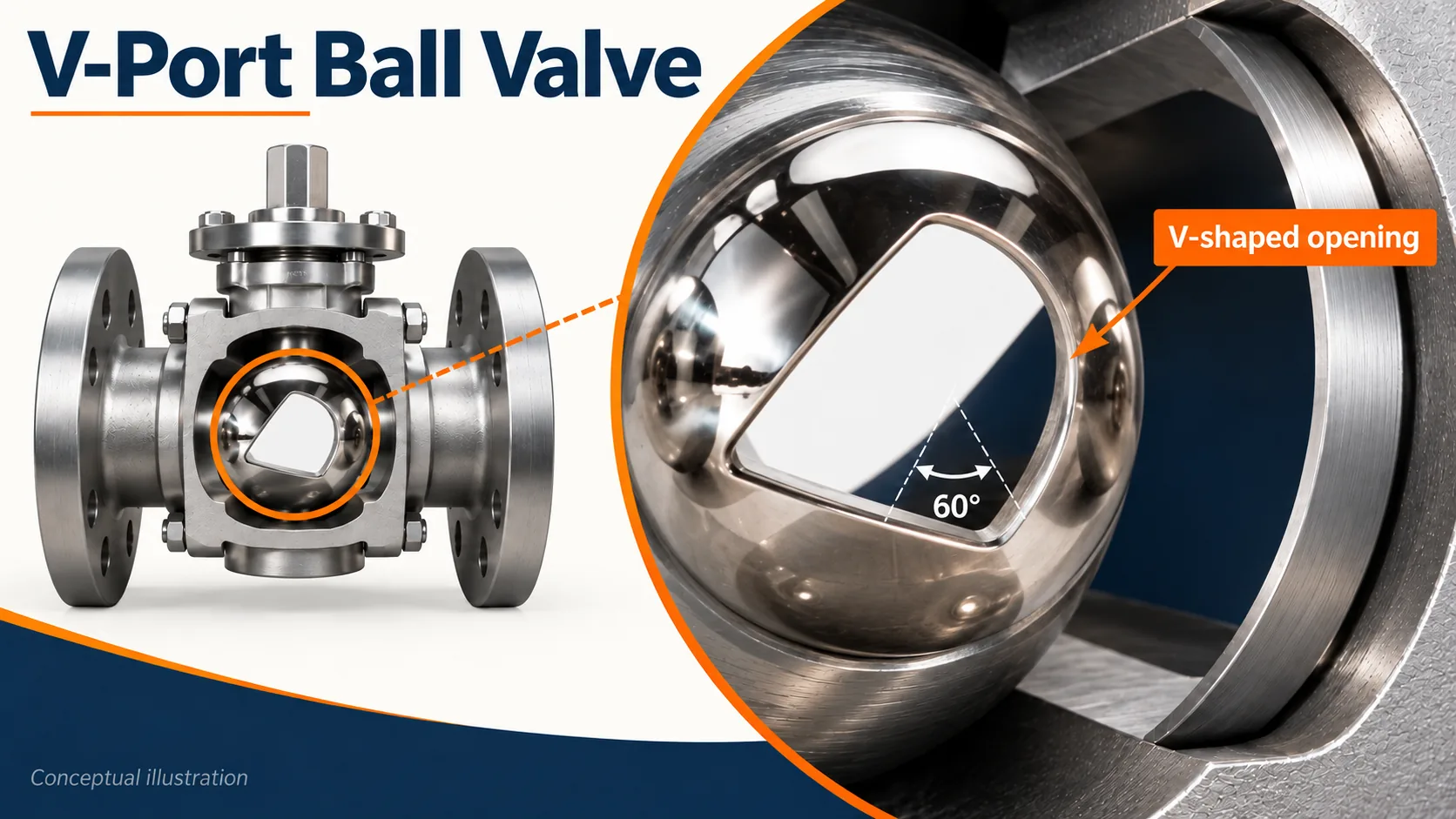
A V-port or segmented-ball design changes the opening geometry to serve a regulating duty. It should be distinguished from a standard full-bore isolation ball valve, whose main job is to open fully or close.
Similarly, some engineered eccentric plug valves regulate flow. The existence of these designs does not make every plug or ball valve suitable for continuous partial opening. Control requires the right flow characteristic, capacity, actuator and position feedback for the process.
Shinjo's V-port ball valve is relevant when the duty calls for modulation. A reader choosing between two ordinary shutoff valves should first decide whether the application actually needs isolation or control; the two duties lead to different comparisons.
For a buyer, this changes the question from which family turns more easily to which trim produces the required installed response. A full-open capacity number cannot describe control across travel. The process needs adequate capacity at the intended operating points without forcing the valve to spend its life in an unsuitable opening range.
The actuator and positioner also belong to the control assembly. A valve intended for modulation needs repeatable positioning under its operating load, whereas an isolation package may be designed mainly to complete two end positions. Substituting one for the other changes the duty even if the pipe connections fit.
Duty | Plug candidate | Ball candidate |
Fully open/fully closed isolation | Rated lubricated, sleeved or other isolation design | Rated full- or reduced-bore isolation design |
Continuous regulation | Engineered eccentric plug control design | V-port or segmented-ball control design |
Flow curve comparison | Offered trim data and installed system conditions | Offered trim data and installed system conditions |
A lubricated plug brings an ongoing sealing-system task; a sleeved plug avoids that particular task but still has serviceable parts. Ball-valve repair access varies by body construction, so it is misleading to call all ball valves disposable or all plug valves easy to dismantle.
The sealing system determines part of the maintenance task; body construction determines how the internals can be reached. These are related but separate decisions.
A lubricated plug valve needs the approved sealant procedure and access to perform it. Sleeved construction avoids that routine interface treatment but can eventually need seat-system service. Neither description establishes how much dismantling is required, what tools are needed or whether the work fits a short shutdown.
Ball valve access varies considerably. Some body constructions are intended for replacement in their installed context; serviceable three-piece and top-entry arrangements provide other repair routes. SLB's Grove BT1 top-entry valve documents access to the ball and seats without removing the body from the line. Such access describes the maintenance arrangement, not permission to open a pressurized valve.
Maintenance task | Plug valve | Ball valve |
Routine interface attention | Approved sealant work if the design requires it | Depends on the seat and any specified servicing provisions |
Internal renewal | Sleeve/seat/plug-system work according to construction | Ball/seat-system work according to construction |
Access planning | Cover, plug-removal and tooling space | Body section or top-entry access and tooling space |
Remaining shared tasks | Stem seals, operator and accessories | Stem seals, operator and accessories |
A maintainable valve can still be difficult to maintain where installed. A removable cover beneath a structural beam, or a body section trapped between rigid pipe runs, may make the advertised access route impractical. Compare the maintenance drawing with the available shutdown space before assigning a serviceability advantage.
Neither family has a defensible universal lifespan advantage. Plug contact can create wear concerns, and ball seats can be damaged by particles or incompatible conditions. The relevant comparison is the failure mechanism in the intended service.
Wear depends on what reaches the sealing surfaces and how they move under load. Abrasive particles, deposits and incompatible fluids can change the outcome for either family. A lower new-valve torque is not a measured service-life advantage, and a larger sealing surface is not a wear-life guarantee.
Maintenance records can help distinguish recurring sealing problems from an isolated operating incident. Useful records identify the medium, operating conditions, observed symptom and parts replaced. They should keep external leakage, seat leakage, travel problems and increasing torque as separate observations. A single label such as “valve failed” obscures the mechanism the replacement needs to address.
A replacement that changes the closure family but preserves the underlying cause may disappoint. For example, a chemical incompatibility affecting the seat system is not resolved merely by exchanging a plug for a ball. The improved choice must change the incompatible material or operating condition. That is where maintenance evidence adds more value than a broad claim of durability.
A conventional plug's sliding contact, an eccentric plug's seat approach and a ball's movement against its seats expose working surfaces differently. Those mechanisms suggest what to investigate; they do not establish a fixed number of cycles. A claim that lower torque automatically means longer life leaves out particle damage, chemistry and temperature.
For infrequent isolation, a long closed dwell followed by reliable breakaway may matter more than continuous cycling endurance. For a frequently operated valve, repeatable movement and retention of the specified leakage performance become more prominent. These are different evidence needs, even when the fluid and nominal valve size are unchanged.
Repairability also differs from durability. A valve whose seats can be renewed conveniently may return to service economically after wear, but that does not prove that its first seat set lasts longer. Compare the expected failure mode, the achievable repair and relevant records separately rather than combining them into one statement that the valve is long-lasting.
Observed problem | Plug-valve question | Ball-valve question |
Increasing effort | Contact condition, deposits, sealant/sleeve and load | Seat condition, deposits, support and load |
Seat leakage | Plug/interface condition and compatible materials | Ball/seat condition and compatible materials |
Difficult restoration | Parts availability and actual plug/seat access | Parts availability and actual ball/seat access |
Ball valves include compact constructions, but neither the lighter valve nor the smaller installed assembly can be identified from the family name. Pressure class, body design and the operator can outweigh the closure-shape difference.
Replacement introduces mechanical constraints as well. Nominal size and class do not establish identical face-to-face length, flange facing, operator clearance or support needs. The proposed flow direction and operating arrangement also need to fit the existing installation. Replacing a plug valve with a ball valve is a specification review, not simply exchanging two quarter-turn handles.
When the existing valve already meets the process duty, replacement can be a decision about serviceability rather than flow. The existing dimensions and access route then become valuable evidence. A lower-cost valve with a different face-to-face length may require a spool change, new supports or a revised actuator position, adding work that is absent from its unit price.
The useful dimensions are face-to-face or end-to-end length, flange/end details, body envelope and the complete operator sweep. A compact body with a long lever may need more usable clearance than a larger body with another operator. An automated assembly also needs space for accessories and for the maintenance route already described.
Weight comparisons should use quoted assembly masses. Bare-valve mass omits a gearbox, actuator, bracket and accessories; installed support needs depend on the complete arrangement. A change to a heavier construction can therefore introduce support or handling work even if the nominal size remains the same.
Replacement item | Compare for both families |
Pipe connection | Actual end type, facing, size and rating |
Installed length | Offered face-to-face/end-to-end dimension |
Operator clearance | Lever sweep or actuator/gearbox envelope |
Support and handling | Complete assembly mass and support arrangement |
Maintenance clearance | Space to remove the specified internal parts |
There is no reliable family-wide rule that plug valves or ball valves cost less. A small standard ball valve, a supported industrial ball valve and a specialized plug valve are different supplied packages. Compare compliant offers before comparing price.
A price comparison is useful only when the offers describe equivalent duties. Size, pressure class, materials, port requirement, actuator, testing and documentation can all change the supplied package. A bare manual valve should not be compared with an automated assembly as though the difference were caused entirely by the closure type.
For an installed valve, consider five cost elements together: valve purchase, operator and accessories, installation changes, planned maintenance, and downtime or eventual replacement. No universal price ratio follows from the plug-versus-ball distinction.
Maintenance access can outweigh a modest difference in purchase price. A design that fits the plant's spare-parts program and shutdown window may be more economical than a cheaper unit requiring pipe removal or unfamiliar tooling. Conversely, a more elaborate serviceable design may offer little value where the site normally replaces the entire assembly and has ready access.
A transparent cost break-even example. Suppose two compliant offers differ in initial installed cost by USD 600. The more expensive offer is expected, under the buyer's own planning assumptions, to avoid USD 150 of service cost per year. Ignoring discounting and all other differences, the simple break-even time is 600 ÷ 150 = four years.
These are hypothetical planning inputs, not market prices, a manufacturer quotation or a claim that one family saves USD 150 each year. The example exposes the assumptions behind a purchasing argument. A claimed maintenance saving has little value unless the plant can explain which task disappears, how often it occurs and what it costs.
The result changes if the avoided annual service cost is only USD 75: the simple period becomes eight years. At USD 300, it becomes two years. This sensitivity is more useful than a single confident payback figure because a maintenance estimate can be uncertain before a new valve has accumulated field history.
Downtime can be added only when its scope is understood. If the valve is serviced during an already scheduled shutdown, charging the whole plant shutdown to that valve would exaggerate the cost. If a repair causes an additional stoppage, the incremental production impact may be relevant. The same logic applies to travel: a dedicated site visit has a different cost from a task performed during an existing visit.
A fair comparison also keeps the decision horizon visible. An installation expected to change soon may never reach a long simple break-even period. A continuously operated asset with a stable service program may place greater weight on later repair access. The price discussion should state the horizon instead of assuming the plant will operate forever.
Cost element | Plug-valve offer | Ball-valve offer |
Purchase | Actual body, port, sealing system and operator | Actual body, bore, seats, support and operator |
Automation | Duty-specific actuator, bracket and accessories | Duty-specific actuator, bracket and accessories |
Installation | Connection changes, supports and access work | Connection changes, supports and access work |
Planned service | Applicable sealant, sleeve/seat and operator tasks | Applicable seat, packing and operator tasks |
Repair or replacement | Real access route, parts and shutdown scope | Real access route, parts and shutdown scope |
An application name identifies the starting problem. The fluid's actual condition, required operation and maintenance environment determine which construction deserves further evaluation.
A suitably rated ball valve is a practical candidate where a large open passage and repeatable automated isolation are priorities. Full-bore and reduced-bore options should be compared against the required capacity rather than selected by name alone.
A plug valve can still meet the duty when its port, sealing system and operation match the requirement. Choosing a familiar valve family is reasonable for standardization, but standardization should preserve a suitable construction rather than copy a nominal size regardless of changed conditions.
A lubricated pressure-balanced plug valve and a trunnion-mounted ball valve can both be candidates. The comparison should address the required isolation function, maximum operating differential pressure, stem sealing and the process's acceptance of sealant contact.
A frequently operated remote valve also brings actuator sizing and failure behavior into the decision. An infrequently operated manual valve raises different access and maintenance questions. Neither is resolved by a generic promise of tight shutoff.
Where a project requires double block and bleed or another isolation arrangement, the seat configuration and test basis must define what the offered valve actually does. A product label cannot settle the required pressure direction or every failure scenario. SLB's WKM 370D series provides an example of ball valves with specified DBB capabilities; that capability belongs to the identified configuration.
An eccentric plug construction deserves consideration because its movement can change how the closure member approaches the seat. That mechanism offers a more useful explanation than the broad claim that plug valves handle dirty fluids better.
Dirty service itself needs definition. Fibrous sludge, settling particles and highly abrasive mineral solids impose different problems. Passage size influences blockage risk, while velocity, particle properties and sealing materials influence wear. A wipe-like motion cannot guarantee that every deposit clears or every abrasive particle passes harmlessly.
A ball valve should not be rejected solely because it has a ball. Its passage, seats and any retained-fluid regions need assessment against the same service. Where the medium can collect in internal spaces, cleaning and shutdown behavior may become as important as open capacity.
The full wetted-material system comes first. A stainless steel body does not establish the compatibility of a sleeve, seat, gasket, O-ring or packing. Normal concentration, contaminants and cleaning fluids belong in the same review.
A sleeved plug valve may be attractive when routine sealant injection is undesirable, provided the sleeve and other internals meet the actual envelope. A compatible ball-valve seat arrangement can be equally relevant. The choice should explain how the proposed materials survive the process, rather than describe one family as inherently corrosion-resistant.
Changes in fluid condition can increase resistance to movement or create deposits around sealing regions. If heating is necessary, a jacketed construction and its interfaces become part of the specification. Shinjo lists steam-jacketed options within its plug valve range, but a jacket does not establish a universal solution for every viscous medium.
The heating conditions, process temperature and expected shutdown state need to agree. A valve that works while the fluid is warm may face a different operating load after the medium cools or solidifies.
Choose a valve designed for control instead of selecting an ordinary shutoff valve and leaving it partially open. V-port ball and engineered eccentric plug control designs are meaningful alternatives, but their capacity, travel behavior and trim limits require process-specific selection. Shinjo's pneumatic control valve guide explains how the valve and actuator fit into the wider control loop.
Three service examples that change the shortlist. The following situations are hypothetical and are intended to show how the same comparison produces different next steps. They are not customer case histories or recommendations for an unspecified hazardous process.
A clean-water transfer line has a limited pressure budget and operates mainly with the isolation valve fully open. Here, full-open capacity and connection fit are prominent. The engineer can compare the actual Cv of a full-bore ball candidate with a plug candidate, then retain whichever constructions also meet the required shutoff and materials. The flow example above provides the calculation method; the real datasheet supplies the inputs.
A remote gas installation has an established lubricated-plug maintenance program but is considering automated operation. Removing the sealant task might be attractive, yet the existing design may already have suitable field support and documented operating behavior. The decision should compare the actuator package and maintenance access of both offers, including the new equipment and training needed if the construction changes. An existing service system has value when it is effective; familiarity alone is not evidence that it remains suitable.
A sludge line experiences deposits and irregular operation. Before replacing the valve with a different family, the team separates fibrous material, settling solids and abrasive particles in the process description. An eccentric plug may address the seating movement problem, while the selected passage and material system must address the actual medium. A change in valve type cannot compensate for an inadequate description of what reaches the seat.
The shortlisting table below is an editorial decision aid, not a product approval matrix.
Application | Plug-valve candidate and benefit | Ball-valve candidate and benefit | Priority for the final choice |
Clean-fluid isolation | A suitable port/sealing system can meet the duty | Full-bore designs are useful starting candidates for low-loss service | Actual Cv/Kv, materials and isolation |
Gas isolation | Pressure-balanced lubricated design where the sealant program is accepted | Rated floating/trunnion construction according to the duty | Isolation arrangement, torque and external sealing |
Sludge or solids-bearing flow | Eccentric movement is worth investigating where solids interfere with seating | An explicitly evaluated passage/seat arrangement may still suit the medium | Solids behavior, velocity and seat interaction |
Sealant-sensitive chemicals | Compatible sleeved construction avoids routine sealant injection | Compatible seats can provide another non-injection option | Complete wetted materials and cleaning envelope |
Viscous or temperature-sensitive fluid | Jacketed plug options may serve a defined heated duty | Evaluate an explicitly suitable ball-valve construction | Temperature control and cooled/shutdown condition |
Continuous regulation | Engineered eccentric control trim | V-port/segmented-ball control trim | Installed capacity and control response |
Choose the starting construction according to the problem the valve must solve. For clean-fluid isolation with a limited pressure budget, compare a full-bore ball valve with a suitably ported plug using actual capacity data. For gas service with an accepted sealant program, compare a pressure-balanced plug and the appropriate ball construction against the isolation and operating requirement. For solids that interfere with seating, investigate the closure motion and seat system rather than applying a blanket dirty-fluid preference.
A ball valve is often the more straightforward starting point when the priority is familiar automated clean-fluid isolation and a large open bore. A plug valve becomes a stronger candidate when its sealing system or eccentric movement delivers a service-specific benefit that the plant can support. Either choice can change when material compatibility, installation fit or repair access becomes the binding constraint.
The following short record makes that final choice concrete without turning the comparison into a procurement manual.
Selection question | Record before accepting either offer |
What duty is required? | Isolation, routing or continuous modulation; frequency and failure action |
What reaches the valve? | Fluid, concentration, solids, temperature and cleaning conditions |
What must it deliver? | Required flow/capacity and defined shutoff performance |
What must it operate against? | Maximum differential pressure and actual power/supply conditions |
Will it fit and remain serviceable? | Connections, dimensions, complete mass and maintenance access |
What is included in the price? | Complete valve/operator scope, documentation, installation and service obligations |
The returned offer should connect materials to the wetted parts, capacity to the offered passage and size, and actuator selection to its operating conditions. A family brochure can show that a feature exists; the configuration-specific documents show whether the quoted assembly includes it. Unanswered questions remain selection tasks rather than implied features.
For a complete enquiry, send those conditions with the maintenance constraint that prompted the comparison. A supplier can then explain why the proposed construction fits the service. That explanation should be specific enough to compare with the alternative rather than relying on the words rugged, tight or low-maintenance.
“Non-lubricated” identifies the absence of routine sealant treatment at a particular sealing interface. It does not eliminate packing, operator or sleeve service. Ask for the maintenance instructions for the complete valve, including the conditions that call for inspection or replacement.
Both families can include multiport designs. The port-position drawing must show the required connections at each operating position, including whether the arrangement permits an unwanted connection during travel. An L-port or T-port label alone is not a complete routing specification.
No. The assembly's pressure-temperature rating concerns its rated service envelope, while the differential pressure across the closure affects operation and actuator sizing. The offered valve must meet both requirements under the relevant conditions.
A ball valve is a useful starting candidate for clean-fluid isolation where the offered bore, seat system and operator meet the flow and service requirements. A plug valve becomes compelling when its lubricated, sleeved or eccentric construction solves a specific sealing or media-handling problem that the plant can support in service.
For gas, solids or demanding chemicals, narrow the comparison to identified constructions before assigning advantages. Match the fluid and duty, establish the flow and sealing requirements, then compare operation and maintenance as installed. Shinjo's plug valves and ball valves provide routes to those candidate designs. The final offer should explain why the chosen assembly fits the application, rather than relying on the name of the valve family.
