A ball valve seals by rotating a bored sphere a quarter turn against two seats. Specify it by more than size and class: floating or trunnion support, full, reduced or V-port bore, body construction, seat material against the maximum temperature at operating pressure, the governing standard (API 6D for pipelines, API 608 or ISO 17292 for process piping, ASME B16.34 for pressure-temperature ratings), the fire, emission and isolation tests, and actuator torque with margin.
A ball valve is a quarter-turn rotary valve that isolates flow by rotating a bored sphere against two seats, and two ball valves with the same size and pressure class can perform very differently in the same line. The words that decide service life sit further down the datasheet: floating or trunnion-mounted support, full, reduced or V-port bore, body construction, seat material and its temperature limit at operating pressure, the governing design standard, the fire, emission and isolation tests the valve has passed, and the actuator's torque margin. Size and pressure class are where the specification starts, not where it ends.
Readers in view are procurement and project engineers specifying against a line list. Sealing is created by line pressure: a floating ball rides onto the downstream seat; a trunnion-mounted ball is held on upper and lower trunnions while spring-loaded seats push upstream. Size and pressure class together decide the crossover. Bore (full, reduced or V-port) changes flow, pigging and modulating capability; body construction from one-piece to fully welded decides whether repair is possible in the line. Virgin PTFE, RPTFE and PEEK seats derate as pressure rises; metal seats serve above the polymer range. DBB, DIB-1 and DIB-2 are ball valve seat configurations defined in API 6D. API 6D, API 608, ISO 17292 and ASME B16.34 each govern different valves. Fire-safe, fugitive-emission, anti-static and sour-service each name a test or a construction requirement. Actuators are sized from breakaway, run and reseat torque through an ISO 5211 flange.
- A ball valve seals by line pressure. Floating balls seat downstream; trunnion seats push upstream onto a fixed ball.
- Size and class together decide trunnion versus floating. Larger bores and higher classes push toward trunnion support.
- Seat material sets the temperature ceiling. Polymer seats derate as pressure rises; metal seats trade tightness for heat.
- Reduced bore costs flow, not isolation. Piggable pipelines still need a full-bore valve.
- DBB and DIB are seat configurations. They are defined in API 6D, not marketing labels for any two-seat valve.
- Fire-safe means a passed fire test. API 607 or ISO 10497 for soft seats, API 6FA for pipeline valves.
- Size the actuator from the highest torque. Breakaway, run or reseat, plus a documented safety factor.
- TL;DR
- Abstract
- Key Takeaways
- How a Ball Valve Works: Quarter-Turn Sealing Explained
- Floating vs Trunnion-Mounted Ball Valves
- Bore and Body Construction: Full, Reduced and V-Port
- Ball Valve Seat Materials and Temperature Limits
- DBB, DIB-1 and DIB-2: Isolation Is a Seat Configuration
- Ball Valve Standards: API 6D, API 608, ISO 17292 and ASME B16.34
- Fire-Safe, Low-Emission, Anti-Static and Sour-Service Features
- Actuators and Torque Sizing for Ball Valves
- By the Numbers
- A Ball Valve Specification Checklist for Your RFQ
- Frequently Asked Questions
- Conclusion
- References
A ball valve is a quarter-turn valve that isolates flow by rotating a bored sphere 90 degrees between two seat rings. Its purpose is on-off isolation: fully open when the bore aligns with the pipe, fully closed when the ball rotates 90 degrees. On a lever-operated valve, the lever parallel to the pipe means open.
A standard ball valve is an isolation valve, not a throttling valve, so specify it to sit fully open or fully closed. Modulating duty needs a V-port design. The gate valve vs ball valve comparison covers when to prefer a quarter-turn over a multi-turn design.
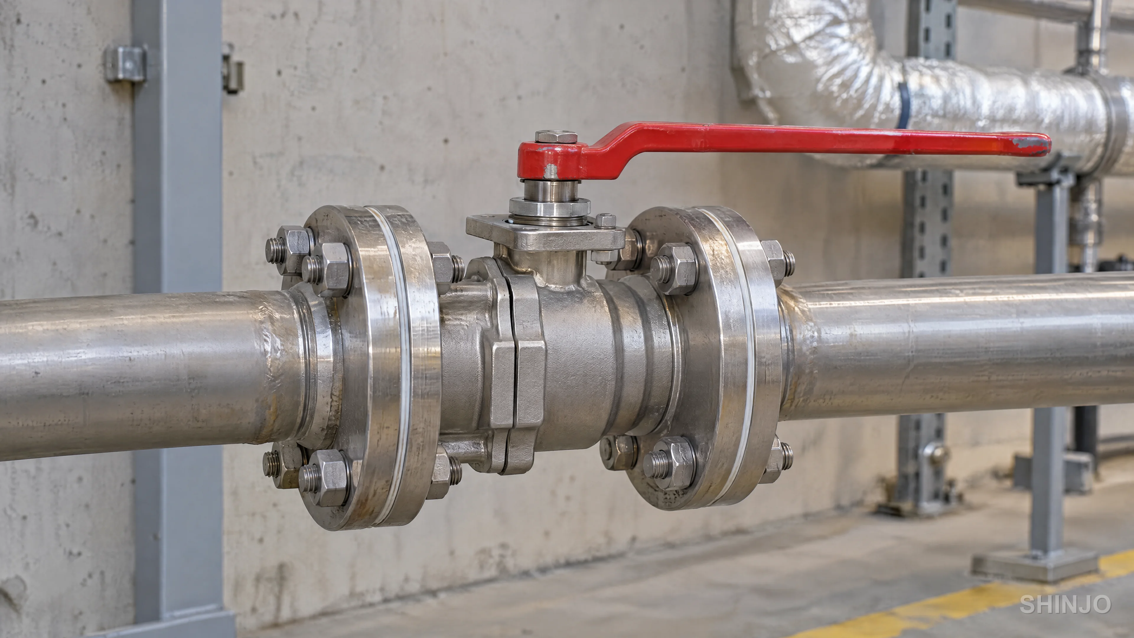
In a floating design, the ball is held only by the two seat rings. Upstream line pressure pushes the ball axially into the downstream seat, so seat contact force rises with differential pressure (Schmitt, 2019). This is downstream seating: the downstream seat carries the pressure load on the ball.
In a trunnion-mounted design, the ball is fixed on an upper and a lower trunnion, and the seats are spring-loaded. Line pressure pushes the upstream seat onto the fixed ball (Valve Magazine, 2021). This is upstream seating: the trunnions carry the pressure load into the body, and seat contact force stays more stable across the stroke.
Line pressure creates the seal in both designs, but from opposite sides. In a floating ball valve, upstream fluid pressure forces the ball onto its downstream seat. In a trunnion-mounted valve, the same pressure forces the upstream seat onto a fixed ball. The support design decides which seat seals (Valve Magazine, 2021).
The consequence for specifiers is direct: in a floating design the seat load and the torque needed to break the ball free both scale with the pressurized bore area, so larger sizes and higher pressure classes push the choice toward a trunnion design. Shinjo's ball valve range lists both families.
The words that appear on every valve datasheet:
- Body: the pressure-containing shell that holds the ball and seats.
- Ball: the spherical closure member with a through-bore.
- Bore: the through-hole in the ball; sets the flow area.
- Seat ring: the sealing ring pressed against the ball on each side.
- Stem: the shaft that transmits rotation from the operator to the ball.
- Trunnion: an upper or lower shaft that supports the ball in a trunnion-mounted design.
- Packing: the stem seal that prevents leakage past the stem to atmosphere.
- Body cavity: the space between the two seats when the valve is closed.
- End connection: how the valve joins the pipe, whether flanged, butt-weld, socket-weld or threaded.
The first specification decision after size and class is how the ball is supported. Two axes decide it together: nominal size and pressure class. Small ball valves at moderate class run economically as floating designs; larger sizes and higher classes push toward trunnion-mounted support. Seat load and operating torque grow with bore area multiplied by differential pressure, and manufacturers publish the crossover as a size-by-class table whose line moves by maker (Valve Magazine, 2021).
A floating ball valve carries the closed-bore pressure load into its downstream seat, so seat contact force and stem torque both rise with bore area multiplied by differential pressure (Schmitt, 2019). A trunnion-mounted ball valve transfers that load into the body through the upper and lower trunnions, leaving the seats to be pushed onto the ball by spring or line pressure alone (Valve Magazine, 2021).
| Attribute | Floating ball | Trunnion-mounted ball |
|---|---|---|
| How the ball is held | Suspended between the two seats | Fixed on upper and lower trunnions |
| Which seat seals | Downstream seat carries the load | Upstream seat pushed onto the ball |
| Torque as pressure rises | Rises with bore area x dP | Lower and more stable across the stroke |
| Typical size and class territory | Smaller sizes, lower classes | Larger sizes, higher classes |
| Cavity pressure relief | Elastic deflection of the soft seat | Self-relieving seats, or external relief |
| Double block and bleed | Not offered as a DBB configuration | Enables DBB with self-relieving seats |
| Relative cost and weight | Lower cost, lighter | Higher cost, heavier |
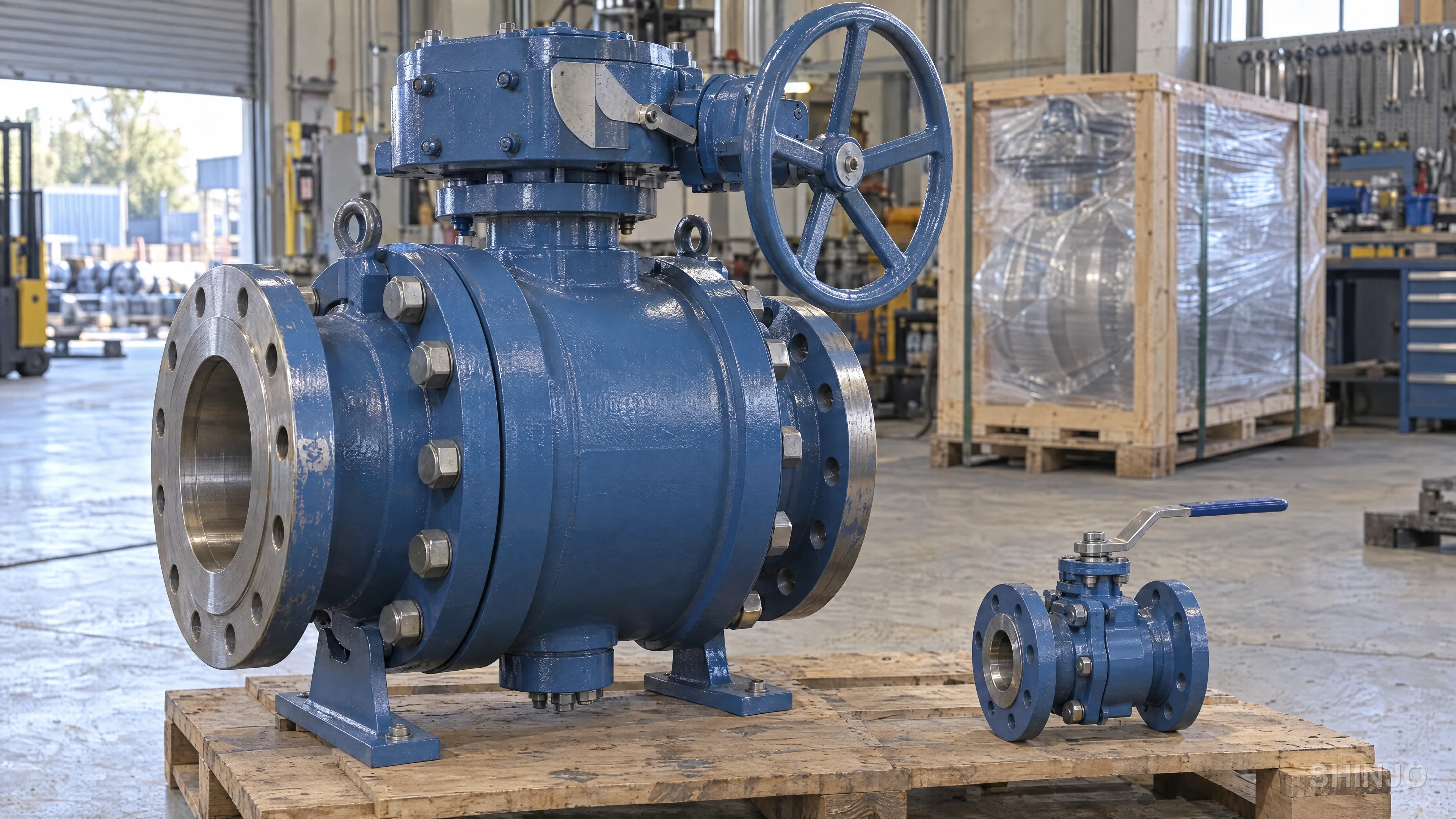
In a floating design the ball is pinned only by the two seats, and the whole pressure force acting on the closed bore transfers into the downstream seat as contact stress (Schmitt, 2019). That force scales with the bore area multiplied by the differential pressure, so a larger bore or a higher class raises the load and both together compound it. At some combination of size and class the soft seat begins to extrude or cold-flow under the contact pressure, and the breakaway torque needed to rotate the ball grows beyond what a practical stem diameter can transmit. Trunnion support carries that pressure force into the body through the upper and lower shafts, so the seats see only their own spring or pressure-energized load, and torque stays lower and more predictable across the stroke. A construction-level comparison lives at floating versus trunnion-mounted design.
The crossover is a torque and seat-load argument, not a mechanical veto, so trunnion construction appears below the usual size and class boundary when torque predictability matters more than cost. Automated service is the common case: an actuator sized for a stable torque profile is smaller, cheaper and more repeatable than one sized for a floating valve whose breakaway grows with line pressure. Frequent-cycling duty, cryogenic service, and any line that will carry a double block and bleed function also justify the trunnion-mounted design at smaller sizes. Ask the vendor for the torque table at operating differential pressure and compare both options at the same duty.
Two datasheet lines often left to the supplier decide flow capacity and whether the valve can ever be repaired in the line: the bore and the body construction. Write both explicitly.
A full bore (also called full port) ball valve carries a ball bore that matches the pipe internal diameter (British Standards Institution, 2015b). Pressure drop is at its lowest, and a pipeline pig can pass through the open valve, which is why piggable pipeline service requires a full-bore design.
A reduced bore design (also called reduced or standard port) uses a ball bore typically one nominal size smaller than the end connection, for example an NPS 2 bore in an NPS 3 valve (British Standards Institution, 2015b). Flow capacity (Cv) drops with the bore area, but isolation performance is unchanged, and the valve costs and weighs less. For general process isolation where a small pressure drop is acceptable, reduced bore is the default choice.
A V-port ball valve replaces the round through-bore with a V-shaped opening in the ball, which gives a characterized flow curve and controllable throttling. This is the ball-valve design meant for modulating duty. For anything more demanding, follow the site's control valve selection guidance rather than repurposing an isolation valve. Deeper background sits in full port versus reduced port and V-port ball valve.
A standard ball valve must not be left partly open. High-velocity flow across the partly exposed seat wire-draws the sealing surface, and the closed valve then leaks. Specify a V-port design or a dedicated control valve for any duty that regulates flow, and keep the standard isolation model only fully open or fully closed.
Body construction decides whether seats can be replaced in the line and how many bolted joints can weep. Five constructions cover the field.
| Construction | How it is built | Repair in the line? | Typical use |
|---|---|---|---|
| One-piece | Single cast or forged body, ball loaded on assembly | No | Small, low-cost, usually reduced bore, non-critical service |
| Two-piece | Body plus one end piece bolted together | No, remove from line first | General process isolation, flanged or threaded ends |
| Three-piece | Center body between two end caps on bolts | Yes, swing the center out | Welded lines, food and pharma, frequent seat replacement |
| Top-entry | Ball and seats accessed through a bolted top cover | Yes, valve stays in line | Large trunnion valves on critical lines |
| Fully welded | All-welded body with no bolted body joints | No | Buried pipeline service where leak paths must be eliminated |
Match the choice to the maintenance plan and to how the ends are joined to the line. A three-piece body pays back on a welded line that needs regular seat changes; a fully welded body suits a buried run where every bolted joint is a future leak, at the cost of cutting the pipe if the valve ever fails.
Seat material, not body material, usually sets a ball valve's temperature ceiling, and that ceiling falls as line pressure rises. Makers publish each seat material's allowable differential pressure against temperature as a curve, so specify against the actual operating pressure and temperature, not the single headline number on a catalog page (Habonim Industrial Valves & Actuators, 2024).
Four seat families cover almost all industrial ball valve service. Virgin PTFE (polytetrafluoroethylene) is the default soft seat: easy to seal, chemically inert, but prone to cold flow at high differential pressure. Reinforced PTFE (RPTFE) adds a glass or carbon filler that resists creep and raises the allowable pressure at a given temperature rather than the temperature ceiling itself. PEEK (polyether ether ketone) is a stiffer thermoplastic used where PTFE families extrude, at the cost of higher operating torque. Metal-seated designs hard-face the ball and seat, typically with tungsten carbide or chromium carbide, and serve above the polymer range and in abrasive or severe duty.
| Seat material | Published maximum temperature (one maker, low pressure) | Strength | Watch out for |
|---|---|---|---|
| Virgin PTFE | 230 °C (446 °F); to 70 bar (Habonim Industrial Valves & Actuators, 2024) | Tight seal, low torque, wide chemical resistance | Cold flow and seat extrusion at high differential pressure |
| Filled PTFE (glass- or carbon-reinforced, RPTFE) | 230 °C (446 °F); to Class 800 (Habonim Industrial Valves & Actuators, 2024) | Same temperature ceiling as virgin PTFE; the filler buys pressure and creep resistance | Fillers can be attacked by strong caustics or oxidizers |
| PEEK (virgin) | 260 °C (500 °F); to Class 2500 (Habonim Industrial Valves & Actuators, 2024) | Higher temperature and higher pressure than PTFE families | Raises breakaway and run torque; check actuator margin |
| Metal-seated (hard-faced) | Above the polymer range; to 650 °C (1,202 °F) for one maker (Habonim Industrial Valves & Actuators, 2024) | Tolerates high temperature and abrasive service | Trades tightness: specified at a looser agreed leakage rate |
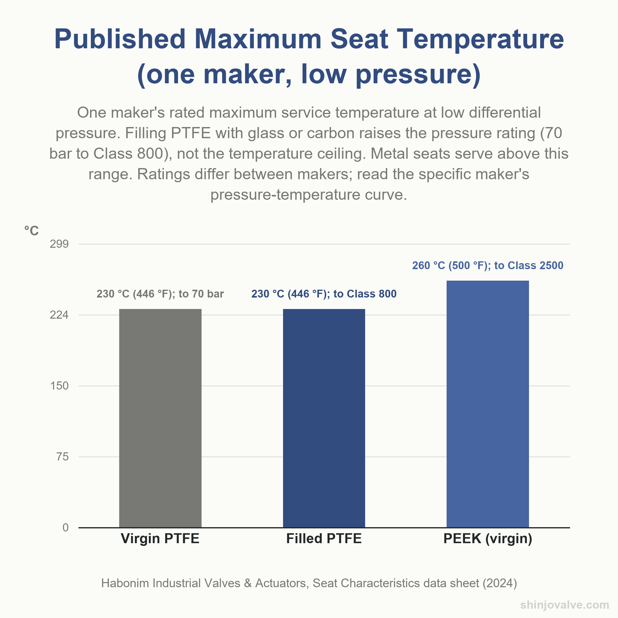
A soft seat seals by deforming against the ball. As line pressure rises, the same polymer that seals also creeps and extrudes past the sealing lip, so the temperature at which the material still holds the ball drops. Every OEM publishes a pressure-temperature curve for each seat family; the specifier reads across from the operating pressure to find the allowable temperature, not from the single number on a catalog page. PTFE families cold-flow fastest, PEEK slowest of the polymers, and a metal seat carries the pressure through direct metal-to-metal contact rather than deformation. That contact wears in its own way: in a component test of a coated stainless steel ball and seat, surface roughness on both rose by a factor of 3 to 4, the seat wore more than the ball, and adhesive and abrasive wear dominated, changes that raise torque and leakage (Bae & Chung, 2016).
A seat material sets the polymer's own ceiling. The body carries a separate pressure-temperature rating governed by its material and pressure class, defined in ASME B16.34 for flanged, threaded and welding-end valves. A carbon steel Class 300 body and a stainless steel Class 300 body derate on different curves, and the seat inside either one derates on its own curve. API 608 turns this into a rule: the valve's pressure-temperature rating is the lesser of the shell rating and the seat rating (SVF Flow Controls, 2018). Specify both limits on the datasheet at the same operating condition, and take the lower as the ball valve's working envelope.
A ball valve specification is not one line on a datasheet, it is several: support design, bore, seat material set against temperature and pressure, the governing standard, and actuator torque with margin. Send the service conditions from your own datasheet, size, class, fluid, temperature and pressure, not just the valve type, and we can match them against Shinjo’s Ball Valves range.
DBB, DIB-1 and DIB-2 describe how a single valve's two seats behave, as API 6D defines them. A double block and bleed (DBB) valve seals against pressure from both ends through two seating surfaces with a bleed between them (American Petroleum Institute, 2021); a double isolation and bleed (DIB) valve seals against pressure from a single source at each seat, with a cavity bleed (American Petroleum Institute, 2021).
DIB-1 carries two bidirectional seats; DIB-2 carries one bidirectional seat and one unidirectional seat (American Petroleum Institute, 2021). Typical seat pairings: DBB uses two self-relieving seats, DIB-1 uses two double-piston-effect seats, and DIB-2 pairs one self-relieving seat with one double-piston-effect seat. The difference decides whether an external cavity relief valve is part of the ball valve specification.
| Configuration | Seat 1 | Seat 2 | Seals cavity pressure? | Needs external cavity relief? |
|---|---|---|---|---|
| DBB | Self-relieving | Self-relieving | No, cavity vents to the line | No |
| DIB-1 | Double-piston-effect | Double-piston-effect | Yes, both seats hold against the cavity | Yes |
| DIB-2 | Self-relieving | Double-piston-effect | Yes, on the DPE side only | Yes |
A self-relieving seat, also called a single-piston-effect seat, is pushed onto the ball by upstream line pressure. When cavity pressure rises above line pressure, most often from thermal expansion of trapped fluid, the seat lifts off the ball and vents the excess back into the line (American Petroleum Institute, 2021). A double-piston-effect (DPE) seat is designed so pressure from either side, upstream or cavity, pushes the seat harder onto the ball. It seals against cavity pressure and cannot self-relieve, so a valve carrying one or two DPE seats needs an external cavity relief valve tapped into the body (American Petroleum Institute, 2021). The direction each seat holds against, and whether it can vent cavity pressure back to the line, is what a specifier writes per seat rather than at the configuration level.
Name the configuration by its API 6D designation, DBB, DIB-1 or DIB-2, not just "double block and bleed." For DIB-1 or DIB-2, list the external cavity relief valve as a separate line item on the RFQ and state its set pressure against the body rating. DIB-1 gives bidirectional isolation on both sides at the cost of the external relief valve; DIB-2 keeps one self-relieving seat and gives up bidirectional isolation on that side. A three-piece trunnion DBB ball valve is the common shape when the line needs isolation from both directions and self-relief through the seats.
Which standard governs a ball valve depends on the service. API 6D, with its international twin ISO 14313, governs pipeline and piping valves for the petroleum and natural gas industries (American Petroleum Institute, 2021). API 608 and ISO 17292 govern metal ball valves for refinery and process piping (British Standards Institution, 2015b; SVF Flow Controls, 2018). ASME B16.34 sets the pressure-temperature rating behind them by body material and pressure class (American Society of Mechanical Engineers, 2020).
| Standard | What it governs | Typical datasheet line |
|---|---|---|
| API 6D (ISO 14313) | Pipeline ball, gate, plug and check valves for petroleum and natural gas service; also defines DBB and DIB configurations. | "API 6D" |
| API 608 | Metal ball valves with flanged, threaded or welding ends for refinery and related process service. | "API 608" |
| ISO 17292 | Metal ball valves for petroleum, petrochemical and allied industries; international counterpart to API 608. | "ISO 17292" |
| BS 5351 (withdrawn) | Former British ball valve standard; withdrawn and replaced by ISO 17292; still cited on legacy datasheets. | Do not specify; use ISO 17292 |
| ASME B16.34 | Pressure-temperature ratings, wall thickness and materials for valves by pressure class (Class 150, 300, 600, 900, 1500, 2500). | "ASME B16.34, Class 300" |
| API 598 | Shell and seat pressure tests for valves outside the API 6D scope. | "API 598" |
| ISO 5208 | Leakage-rate classification for metallic valves: Rate A is no visible leakage for the test duration, and successively looser rates follow. | "ISO 5208 Rate A" |
| EN 12266-1 | European pressure-test standard for metallic valves. | "EN 12266-1" |
The first question is whether the valve sits on a pipeline or on process piping. API 6D, with international twin ISO 14313, covers pipeline valves for petroleum and natural gas service, and it is also the document that defines DBB, DIB-1 and DIB-2 (American Petroleum Institute, 2021). For refinery and process-piping duty, API 608 governs metal ball valves with flanged, threaded or welding ends, and ISO 17292 is the international counterpart (British Standards Institution, 2015b; SVF Flow Controls, 2018). BS 5351 was the former British ball valve standard; it has been withdrawn and replaced by ISO 17292, though it still appears on older datasheets (Health and Safety Executive, n.d.). For a side-by-side view of the two American documents, see our note on API 6D versus API 608.
ASME B16.34 sets pressure-temperature ratings, wall thickness and materials for flanged, threaded and welding-end valves. A pressure class is a rating by body material and temperature, not a single test pressure. The valve is rated at Class 150, 300, 600, 900, 1500 or 2500, and the allowable working pressure at any operating temperature is read from the class table for the specific material (American Society of Mechanical Engineers, 2020). The standard also distinguishes Standard, Special and Limited class designations, which differ in inspection, non-destructive examination and test rigor. Name the standard and the class on the datasheet; the supplier returns the specific pressure at the specified temperature.
For valves outside the API 6D scope, purchase orders commonly call for shell and seat pressure testing to API 598. ISO 5208 classifies seat leakage by rate: Rate A is no visible leakage for the test duration, and successively looser rates follow (British Standards Institution, 2015a). Soft-seated ball valves are normally tested to zero visible leakage; metal-seated valves are specified at a looser rate agreed between buyer and supplier, and that agreed rate should appear on the purchase order alongside the acceptance criterion. For reference, the Shinjo ball valve category page lists design standards including API 6D, ASME B16.34, EN ISO 17292 and BS 5351.
Each of these words on a ball valve datasheet names either a passed test or a construction requirement, and a specification should carry the standard behind it, not the word alone. "Fire-safe design" without a fire-test report and "low-emission" without a tightness class commit the supplier to nothing measurable.
Fire-safe means the design has passed a fire type test: API 607 or ISO 10497 for quarter-turn and soft-seated valves, API 6FA for valves within the API 6D scope. The test burns the closed valve and measures leakage through the seat and to the outside, including after cooldown (Valve Magazine, 2015).
A soft seat burns away in a hydrocarbon fire, and the fire-safe design carries a secondary metal-to-metal seal that takes over so the closed valve still limits leakage after the elastomer is gone. The certificate qualifies a design, not each production valve, and it names the tested size range and pressure class. A valve outside that range is not covered by the design's approval.
Specifier note: "fire-safe design" on a catalog page is a design claim, not evidence of a passed test. Ask for the fire-test report or certificate that covers the specific valve family, size and pressure class you are ordering, not a generic brochure line.
ISO 15848-1 qualifies the stem seal by type test and classifies it on two axes: tightness class (A tightest, then B, then C) and endurance class (CO1, CO2 and CO3 for on-off valves, by number of mechanical cycles) (British Standards Institution, 2025). State both classes on the datasheet, together with the test temperature and pressure, so the specification matches what the site emissions program requires.
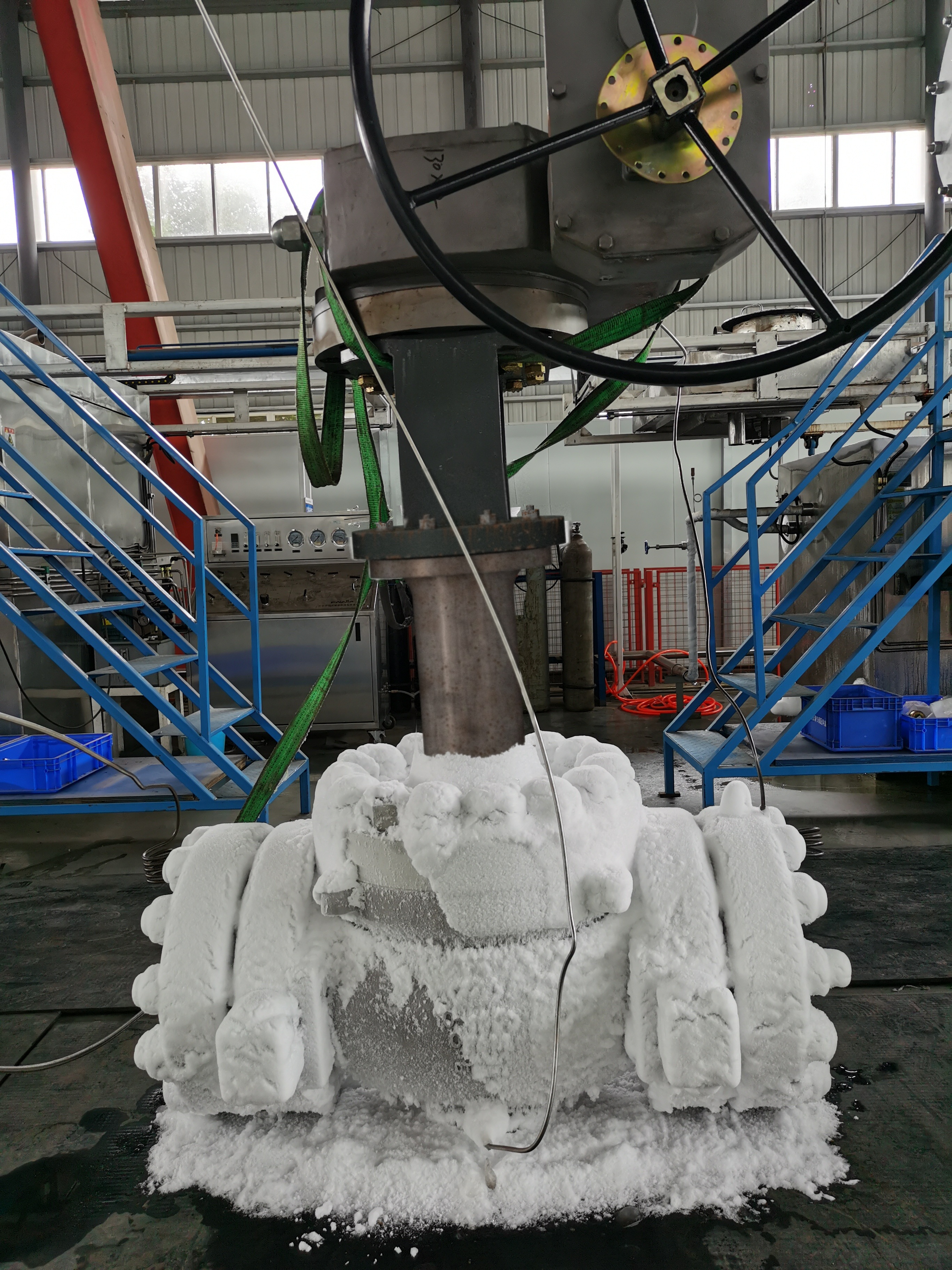
Anti-static construction places a spring-loaded contact between ball, stem and body so electrostatic charge from flowing fluid cannot build up in flammable service; API 608 and ISO 17292 both require the feature and specify that the measured resistance shall not exceed 10 ohms at a test voltage not greater than 12 V DC (British Standards Institution, 2015b; SVF Flow Controls, 2018). A blowout-proof stem is inserted from inside the body, so line pressure cannot push it out even if the gland packing is removed for maintenance. For cryogenic service, an extended bonnet keeps the stem packing away from the cold zone; BS 6364 covers valves for cryogenic service (British Standards Institution, 1998). A photograph of a cryogenic ball valve with an extended bonnet makes the geometry visible. For sour service, NACE MR0175 / ISO 15156 limits the hardness of wetted metals to resist sulfide stress cracking; for carbon steel the common limit is 22 HRC (British Standards Institution, 2020).
Size the actuator from the highest of breakaway, run and reseat torque published for the valve at its seat, size and differential pressure, then multiply that peak by a documented safety factor. The actuator must still deliver this torque at the MINIMUM available supply pressure or voltage; sizing at nominal supply is how automated valves stall on a bad day.
Valve makers publish torque as three numbers: the peak at unseating (breakaway), the running torque through mid-stroke, and the peak at end of travel when the seat re-engages (reseat). Owner practice multiplies the highest of the three by a safety factor between 1.25 and 2.0 to size the actuator, higher for dirty, cold or infrequently operated service.
Breakaway is the torque needed to lift the ball off the seat from a closed, static position. It rises with differential pressure and time in service. A soft-seated valve left closed under pressure and temperature for weeks develops higher breakaway than a new one because the seat has crept around the ball. Run torque is the lower value the actuator sees through mid-rotation. Reseat torque climbs again at end of travel as the seat re-engages. Sizing to run torque alone is a common cause of stalled automated valves. The maker's torque data for trunnion-mounted ball valves shows the shape of these curves.
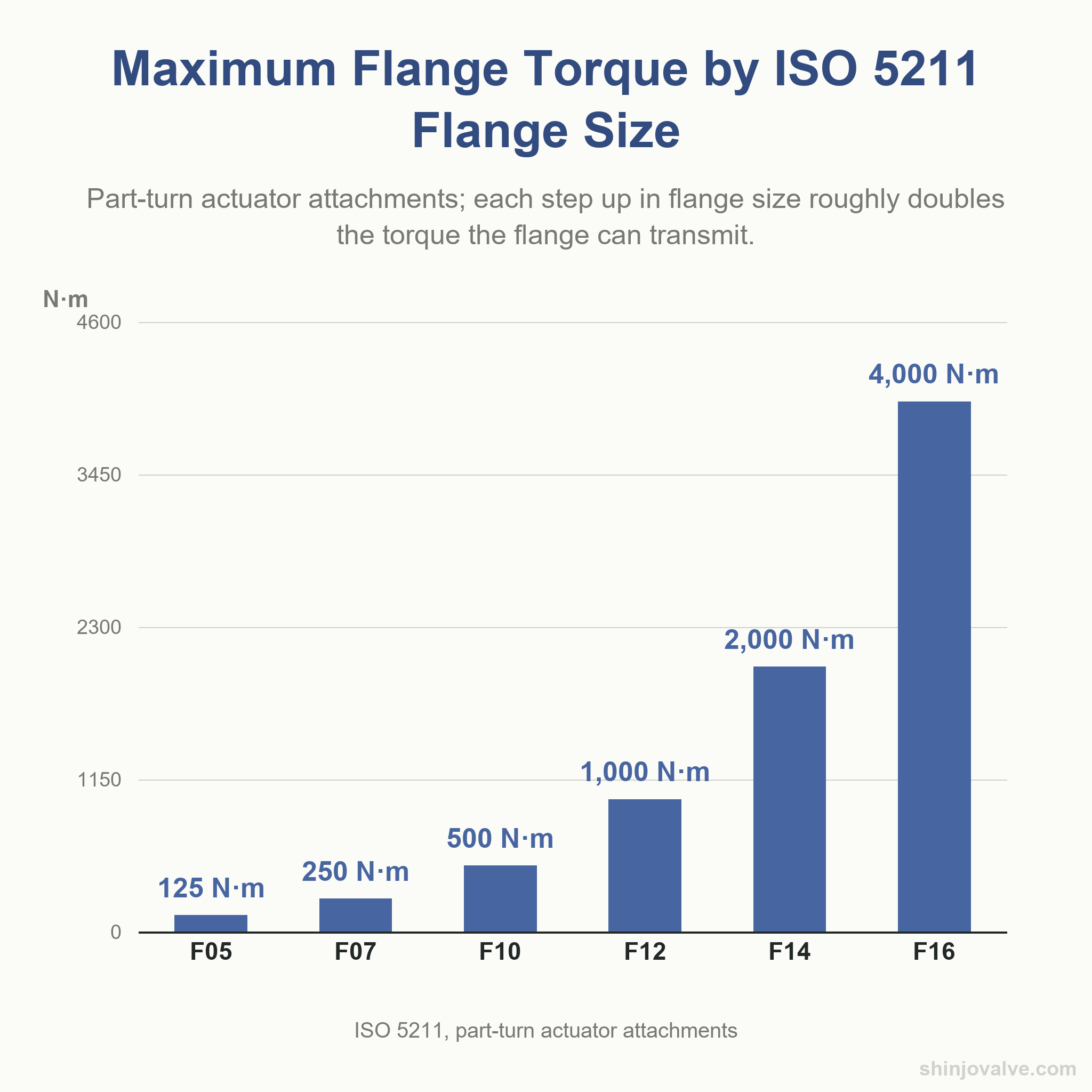
ISO 5211 standardizes the actuator mounting flange and drive coupling so any actuator with an F10 output bolts to any valve with an F10 mounting flange (British Standards Institution, 2023). Each step up in flange size roughly doubles the torque the flange transmits:
| ISO 5211 flange | Maximum flange torque (N·m) |
|---|---|
| F05 | 125 |
| F07 | 250 |
| F10 | 500 |
| F12 | 1,000 |
| F14 | 2,000 |
| F16 | 4,000 |
Actuator type follows the duty: pneumatic rack-and-pinion or scotch-yoke for on-off service, electric for slower or line-powered applications, hydraulic for very high torque, plus a lever or bevel gear operator for manual duty. Fail-safe action is set at the actuator: a double-acting cylinder holds the last commanded position on air loss, while a spring-return unit drives the valve to a defined fail-open or fail-closed position on loss of supply. The fail position is a process safety decision, not a supplier default, and belongs on the RFQ.
- 230 °C virgin and filled PTFE seat ceiling at low pressure (Habonim Industrial Valves & Actuators, 2024)
- 260 °C PEEK seat ceiling with wider pressure envelope (Habonim Industrial Valves & Actuators, 2024)
- 650 °C metal-seated ceiling reported by one maker (Habonim Industrial Valves & Actuators, 2024)
- 3 to 4 factor of rise in ball and seat surface roughness after metal-seat wear (Bae & Chung, 2016)
- 10 ohms anti-static resistance ceiling under API 608 and ISO 17292 (British Standards Institution, 2015b; SVF Flow Controls, 2018)
- 22 HRC hardness limit for carbon steel in sour service (British Standards Institution, 2020)
A quotation for a ball valve is only as exact as the service conditions sent with it.
An RFQ for a ball valve must carry 13 lines: the line size and end connection, pressure class, service fluid with its temperature and pressure extremes, support design and bore, materials, design and rating standards, isolation configuration, fire and emission requirements, seat leakage rate, operator with fail position, and the documents required at delivery.
- Size and end connection: NPS or DN with flange standard and facing, butt-weld, socket-weld or threaded ends per the piping specification.
- Pressure class: Class 150, 300, 600, 900, 1500 or 2500, or the matching PN rating.
- Service conditions: fluid name and phase, maximum and minimum temperature, maximum operating and differential pressure at the closed valve.
- Support design: floating or trunnion-mounted, matched to the size and class in the maker's own crossover table.
- Bore selection: full, reduced or V-port, with full bore stated for any piggable pipeline and V-port for modulating duty.
- Body construction: one-piece, two-piece, three-piece, top-entry or fully welded, chosen for the required repair strategy.
- Materials of construction: body, ball, stem and seat, each named for the service fluid and temperature.
- Design and rating standards: API 6D, API 608 or ISO 17292 for the design, with the ASME B16.34 pressure-temperature rating.
- Isolation configuration: DBB, DIB-1 or DIB-2 per API 6D, and whether an external cavity relief valve is required.
- Safety features: fire test (API 607, ISO 10497 or API 6FA), emission class (ISO 15848-1), anti-static, and NACE MR0175 sour-service limits.
- Seat leakage test: ISO 5208 rate or API 598, zero visible leakage for soft seats or the agreed rate for metal seats.
- Operator specification: lever, gear or actuator with the ISO 5211 flange, supply pressure and fail-open or fail-closed position.
- Required documents: material certificates, shell and seat test reports, and any fire, emission or sour-service test records.
The Shinjo ball valve category page lists floating, trunnion-mounted and V-port designs across the size and class range shown there, and a request for quotation that carries the lines above can be matched item by item against what Shinjo supplies.
A ball valve is used for on-off isolation of flow in a pipeline. A quarter turn of the stem rotates a bored sphere between two seats: bore aligned with the pipe is open, bore rotated 90 degrees is closed. It is not designed for throttling.
'Standard valve' usually means a multi-turn gate or globe valve. A ball valve is a quarter-turn rotary valve for isolation; a gate valve needs many stem turns to open and closes with a wedge. For a full comparison, see gate valve vs ball valve.
Lists vary by source and no single body publishes an official 'seven types'. The families common to most classifications are gate, globe, ball, butterfly, plug, check and diaphragm valves. Each closes flow differently: a ball valve isolates with a quarter turn, a check valve prevents reverse flow.
The cost depends on size, pressure class, body and seat material, whether the valve is manual or actuated, and the installation labor to isolate, drain and refit the line. A firm quotation needs a full valve specification, so a supplier can price the exact valve and the work.
Size and pressure class together decide it. Floating designs suit smaller sizes and lower classes, where seat load and operating torque remain manageable; trunnion-mounted designs carry the pressure load into the body through the trunnions and take over as bore and class rise. Read the maker's size-by-class crossover table.
'Fire-safe' means the design has passed a fire type test: API 607 or ISO 10497 for soft-seated quarter-turn valves, API 6FA for pipeline valves. The burned closed valve is then measured for seat and external leakage. A secondary metal-to-metal seal takes over when the soft seat burns away.
DBB (double block and bleed) seals against pressure from both ends with two self-relieving seats that vent excess cavity pressure into the line. DIB-2 (double isolation and bleed) has one self-relieving seat and one double-piston-effect seat, which seals cavity pressure and needs an external cavity relief valve.
PTFE-family seats are rated by at least one maker to about 230 °C (446 °F) at low pressure; glass or carbon filling raises the pressure rating, not the ceiling. PEEK reaches about 260 °C (500 °F) with far more pressure capacity. Above that, specify metal seats and an agreed ISO 5208 leakage rate, and check each maker's pressure-temperature curve.
Size and pressure class are where a ball valve specification starts, not where it finishes. Two valves that match on nominal diameter and class can behave differently in service because the decisions that follow them decide how long the valve will hold. Support design sets the load path and the torque the actuator must overcome. Bore choice sets flow capacity and whether the line can be pigged. Body construction sets whether the valve can be repaired in place or must be cut out. Seat material sets the temperature ceiling at the operating pressure, and metal seats extend the range where polymer seats cannot go.
The governing standard, and the fire, emission, isolation and sour-service tests behind it, decide what the supplier is committing to when the words are printed on a nameplate. Actuator sizing, based on the highest of breakaway, run and reseat torque with a documented safety factor at minimum supply, sets whether the valve strokes reliably or stalls in a fault condition. A specification that names all of these lines gives a buyer a ball valve that will hold, and gives a supplier what it needs to quote one.
- American Petroleum Institute. (2021). Specification for pipeline and piping valves (API 6D, 25th ed.). API. https://www.api.org/products-and-services/standards/important-standards-announcements/spec6d
- American Society of Mechanical Engineers. (2020). Valves - Flanged, threaded, and welding end (ASME B16.34-2020). ASME. https://www.asme.org/codes-standards/find-codes-standards/b16-34-valves-flanged-threaded-welding-end
- Bae, J., & Chung, K.-H. (2016). Wear characteristics of metal ball and seat for metal-seated ball valve. Journal of the Korean Society of Tribologists and Lubrication Engineers, 32(1), 32–38. https://doi.org/10.9725/kstle.2016.32.1.32
- British Standards Institution. (1998). Specification for valves for cryogenic service (BS 6364:1998). BSI. https://doi.org/10.3403/01681278
- British Standards Institution. (2015a). Industrial valves - Pressure testing of metallic valves (BS ISO 5208:2015). BSI. https://doi.org/10.3403/30302783
- British Standards Institution. (2015b). Metal ball valves for petroleum, petrochemical and allied industries (BS EN ISO 17292:2015). BSI. https://doi.org/10.3403/30299750
- British Standards Institution. (2020). Petroleum and natural gas industries - Materials for use in H2S-containing environments in oil and gas production - Part 2: Cracking-resistant carbon and low-alloy steels, and the use of cast irons (BS EN ISO 15156-2:2020). BSI. https://doi.org/10.3403/30404500
- British Standards Institution. (2023). Industrial valves - Part-turn actuator attachments (BS EN ISO 5211:2023). BSI. https://doi.org/10.3403/30472790
- British Standards Institution. (2025). Industrial valves - Measurement, test and qualification procedures for fugitive emissions - Part 1: Classification system and qualification procedures for type testing of stem seals for valves (BS EN ISO 15848-1:2025). BSI. https://doi.org/10.3403/30444462
- Habonim Industrial Valves & Actuators. (2024). Seat characteristics [Data sheet]. Habonim. https://habonim.com/wp-content/uploads/2024/11/Seat-Characteristics-v2.pdf
- Health and Safety Executive. (n.d.). British Standards Institution (BSI) [Status list of British Standards, including BS 5351]. U.K. Health and Safety Executive. https://www.hse.gov.uk/comah/sragtech/docsbsi.htm
- Schmitt, D. (2019, April 25). Functionality and seating technology for floating ball valves. Processing Magazine. https://www.processingmagazine.com/process-control-automation/instrumentation/article/55350466/functionality-and-seating-technology-for-floating-ball-valves
- SVF Flow Controls. (2018, November 7). API 608 standard for valve requirements [Tech brief No. 1089]. SVF Flow Controls. https://svf.net/application/files/8517/0896/4414/Tech-Brief-1089-API-608-Standard-for-Valve-Requirements.pdf
- Valve Magazine. (2015). The past, present and future of fire testing. Valve Magazine. https://valvemagazine.com/articles/the-past-present-and-future-of-fire-testing
- Valve Magazine. (2021, August 9). Ball valve basics. Valve Magazine. https://valvemagazine.com/articles/ball-valves-basics
Last reviewed and updated: September 2026. Author: Shinjo Valve engineering team. For valve selection support or a quotation against your service conditions, contact our team.
