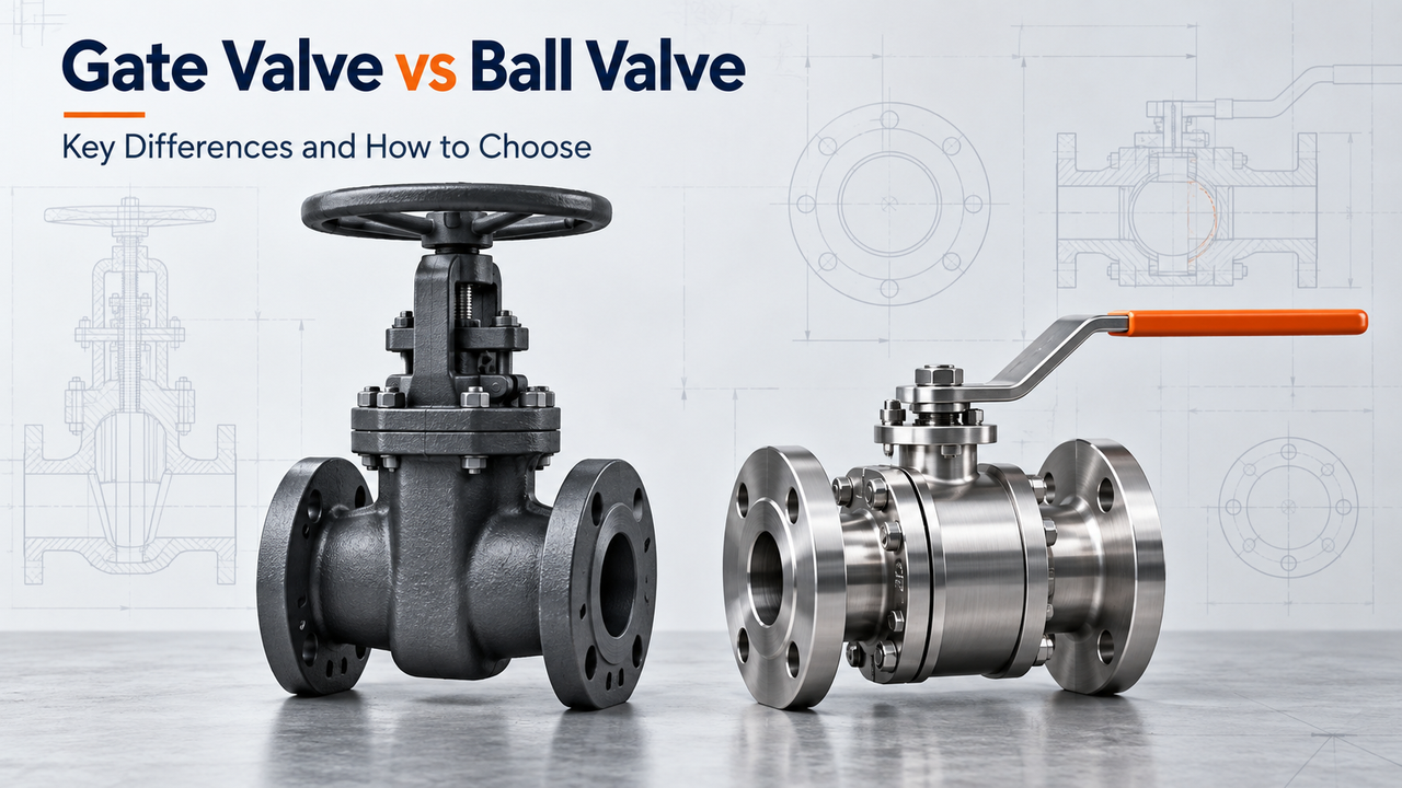
On a P&ID, a gate valve and a ball valve may both appear as simple isolation points. In service, however, they behave differently. Ball valves are often well suited to fast, repeatable on/off operation and compact automation, while gate valves are commonly used for isolation where the valve remains fully open or fully closed for long periods. The right choice depends on the process conditions, operating frequency, line layout, and specific valve construction.
The valve type alone does not define its suitability. A full-port floating ball valve, a metal-seated trunnion ball valve, a resilient-seated gate valve, a slab gate valve, and a knife gate valve are designed for different operating conditions. Before selecting a valve, define the required shutoff duty, pressure and temperature range, process medium, operating method, and maintenance requirements, then verify these conditions against the supplier's documentation for the proposed model.
| If the line needs... | Better starting point | What must still be verified |
| Fast or frequent on/off isolation | Ball valve | Seat material, pressure differential, operating torque, cycle frequency, and closure speed |
| Straight-through isolation with the valve normally fully open or fully closed | Gate valve | Gate design, stem arrangement, pressure-temperature rating, and installation clearance |
| Compact remote operation | Ball valve | Actuator torque, fail position, cycle time, control signal, mounting, and area classification |
| Predictable flow control at partial opening | Neither standard valve by default | Consider a purpose-selected V-port ball valve or control valve sized for the required flow conditions |
| A large line where cost and installation space matter | Compare gate, ball, and butterfly valves | Bore size, pressure class, face-to-face dimensions, actuation method, shutoff requirements, and total installed cost |
| Steam, abrasive solids, corrosive media, or high temperatures | Start with the process conditions, not the valve family | Medium composition, contaminants, temperature, pressure, wetted materials, seats, packing, and applicable standards |
This table is a starting point, not a final valve specification. Ball valves are available in full-port and reduced-port designs, while gate valves include wedge, slab, knife, resilient-seated, pressure-seal, and bellows-sealed configurations. The final choice depends on the specific design, materials, pressure and temperature conditions, and required operating duty.
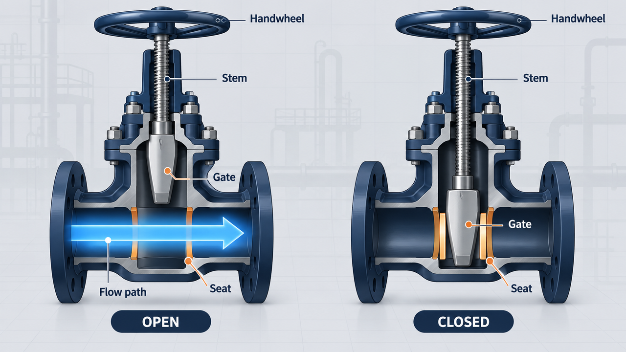
A gate valve uses a gate that travels across the flow passage. Turning the handwheel or operator moves the stem, raising the gate away from the passage to open it or lowering the gate onto its seats to shut it. The travel is multi-turn rather than quarter-turn. In a rising-stem construction, stem movement can make the valve position easier to observe, but it also needs vertical clearance. A non-rising-stem design can suit restricted headroom, although position indication needs its own review.
When fully open, a conventional gate arrangement can offer a straight flow path with little obstruction from the closure member. That is attractive in isolation duties where the valve is expected to stay open for long periods and where line resistance, access arrangement or a multi-turn operating procedure matter. Shinjo's published gate valve range includes resilient-seated, slab, knife, bellows-sealed, pressure-seal, cryogenic and actuated configurations, which is a useful reminder that “gate valve” is the beginning of selection, not the end.
The gate itself is not one universal component. A wedge gate seats by moving down between seats; a slab gate uses a different geometry and is commonly considered where a clear bore or pipeline-specific arrangement matters; a knife gate is designed around a different set of solids-handling problems. Stem arrangement changes the field experience too. A rising stem consumes vertical space but can make travel more visible, while a non-rising stem may help in low headroom but calls for reliable indication. These details should be settled before a layout drawing is frozen, not after a valve has been ordered.
A standard gate valve is not a general throttling device. When it is left partly open, the flow is forced through a narrow, unstable restriction around the gate. That can create local velocity, vibration and wear around the gate and seats; the eventual result may be poor shutoff when the valve is later needed for isolation. Shinjo's own gate-valve guidance states that gate valves should not be used for throttling unless specifically approved. Tameson's comparison guide likewise identifies the multi-turn operating difference, but the practical implication matters more than the mechanism: do not solve a daily flow-control problem by leaving a normal gate partly open.
Gate-valve advantage | What it can mean in practice | Limitation to test before selection |
Gate moves out of the passage when fully open | Can suit an isolation line where an unobstructed open path matters | The actual design must still be fully open and the bore/drawing must meet the hydraulic requirement |
Multi-turn operation | Can fit a controlled, infrequent isolation routine | It increases operation time and can complicate remote actuation or emergency response |
Broad construction family | Wedge, slab, knife, resilient and pressure-seal designs address different duties | A category name does not establish suitability for steam, solids, pressure or shutoff class |
Familiar isolation arrangement | May suit an existing plant standard, layout or maintenance practice | Older or rarely exercised valves may not deliver dependable shutoff when a shutdown finally occurs |
Read the table as a set of trade-offs. A straight open path has little value when the valve will routinely sit half open, and a lower initial price does not help if the operating arrangement cannot support an emergency procedure. The job decides whether the apparent advantage is useful.
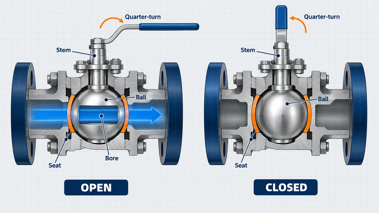
A ball valve uses a drilled, rotating ball. With the bore aligned to the pipeline, flow can pass through; rotate the ball by roughly 90 degrees and the solid side blocks the passage. A lever normally gives a quick visual cue because it is commonly aligned with flow when open and across the pipe when closed. Gear operators and actuators can change the external arrangement, but the closure member still has quarter-turn travel.
Quarter-turn movement suits quick manual isolation and is often convenient where a valve must be cycled or automated. It can also give a compact actuator package compared with a multi-turn arrangement. Shinjo documents floating, trunnion-mounted, top-entry, two-piece, three-piece, metal-seated, PTFE-seated, low-temperature, steam-jacketed, pneumatic and motorized ball valve configurations. Those options matter because seat material, mounting, body style and ball support alter the real operating limits.
Floating and trunnion-mounted ball valves should be treated as distinct designs, not as alternative names for the same product. A floating ball is supported differently from a trunnion-mounted ball, which changes the way the assembly carries load and the torque discussion that follows. Bore also matters: full-port and reduced-port models can share the same nominal pipe size while presenting different internal passages. For a line that must pass cleaning tools, protect a pressure-drop allowance, or handle a viscous medium, ask for the bore dimension and general arrangement drawing rather than relying on the word “full bore” in a sales description.
A conventional ball valve is still an isolation valve unless its construction and operating duty say otherwise. Holding an ordinary ball at an arbitrary angle does not create a stable control characteristic, and it can expose seats to a duty they were not selected to handle. A V-port ball valve can be a valid engineering route for some controlled-flow duties, but it requires flow, pressure-drop, noise, cavitation, flashing, materials and actuator review. If the process truly needs continuous regulation, compare a purpose-selected globe valve or another control-valve arrangement instead of treating every ball valve as a control valve.
Ball-valve advantage | What it can mean in practice | Limitation to test before selection |
Quarter-turn movement | Fast local isolation and a compact starting point for automation | The required closure profile may need to be slowed to protect a liquid system from surge |
Direct position cue on many manual handles | Operators can often see the intended open/closed orientation quickly | Gearboxes, actuators and local procedures can change how position must be confirmed |
Multiple body, seat and ball-support designs | The family can be adapted to a wide range of isolation duties | Floating, trunnion, soft-seated and metal-seated designs are not interchangeable |
Potentially serviceable construction | Some designs allow a planned maintenance strategy around seats and seals | The maintenance route, spares, torque after aging and line-removal requirement remain model-specific |
“Use a ball valve for shutoff” is only a first direction. The purchase decision still needs the body, ball support, bore, seats, stem sealing, ends, pressure class, operator or actuator, test scope and documents to be defined as one package.
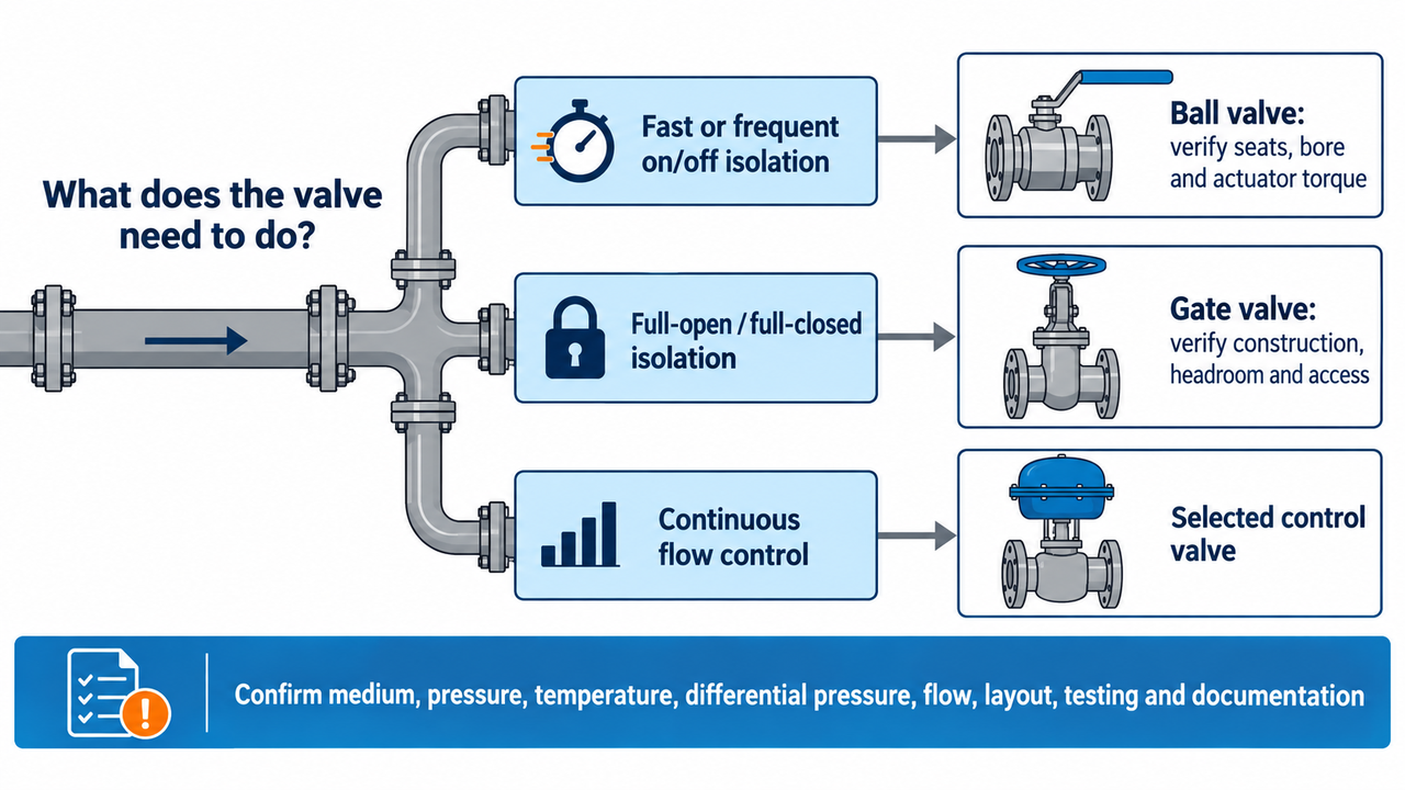
The practical difference between a gate valve and a ball valve is not the shape of the closure member. It is what that mechanism asks of the operator, the piping system and the maintenance team once the valve is installed. A ball valve turns a drilled ball through a quarter turn; a gate valve raises or lowers a gate through multi-turn travel. That single design difference affects closing time, actuator choice, available headroom, flow-path review and the way each valve behaves when someone tries to use it for a job it was not selected to do.
For most ordinary isolation duties, a ball valve is the first option to consider when fast, repeatable on/off operation or quarter-turn automation matters. A gate valve remains a valid starting point where the valve will stay fully open or fully closed, the selected gate construction suits the service, and the layout has room for its operating arrangement. Neither answer is complete until the exact fluid, temperature, pressure differential, cycle duty, bore, materials and required documentation are known.
Quick decision: Choose the valve around its job. If the line needs to change flow continuously, neither a standard gate valve nor a standard ball valve should be selected simply because it can be left partly open. That is a control-duty question and needs a purpose-selected control solution.
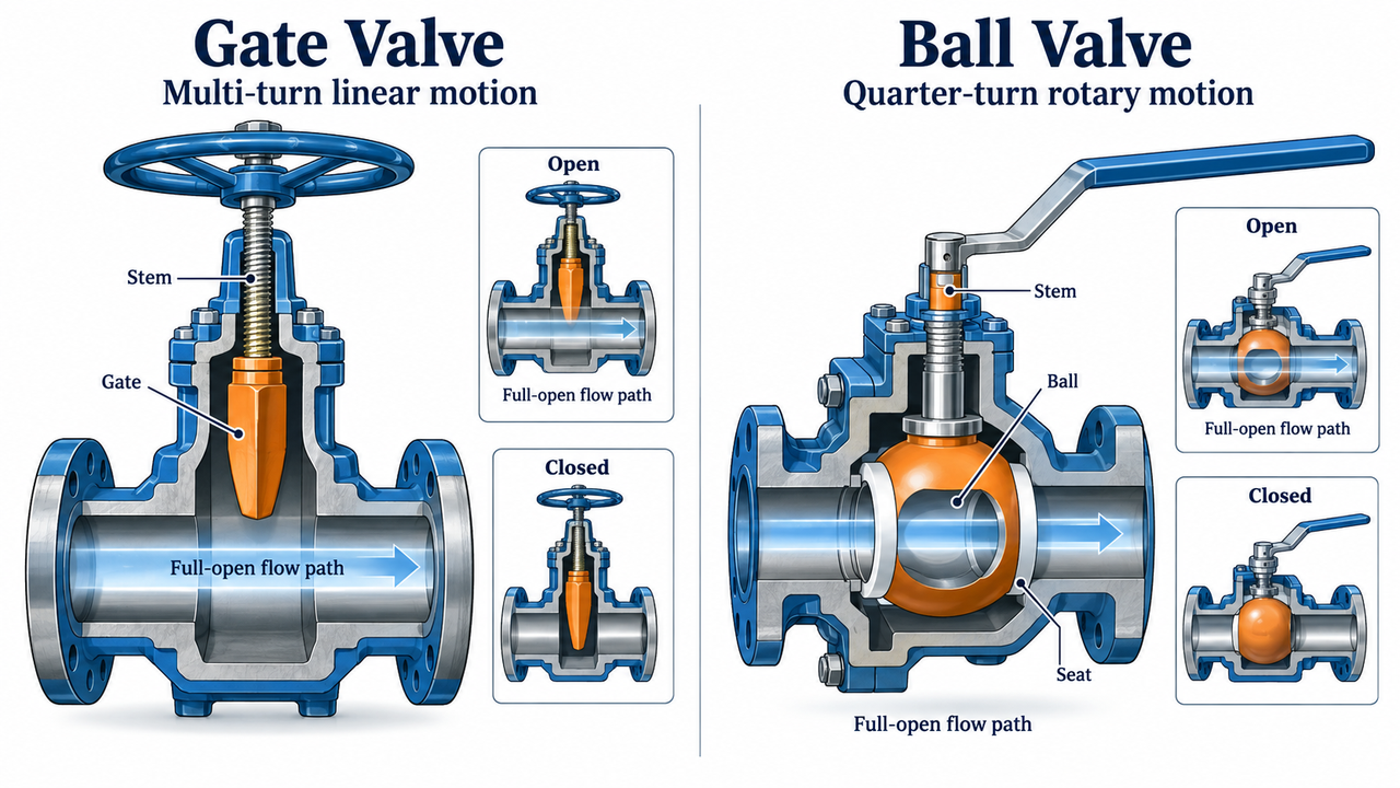
A ball valve normally needs about 90 degrees of movement from open to closed. For a local operator, that can mean one predictable handle movement. For an automated package, it often means a compact quarter-turn actuator with straightforward travel. This is why ball valves are frequently considered for equipment isolation, emergency shutoff logic and sequences where a valve has to operate repeatedly.
A gate valve takes multi-turn motion to move the gate between its end positions. The operator may turn a handwheel, use a gearbox or rely on a motorized actuator. Slower movement may suit a line intended to remain open for long periods, but it is not a universal advantage. The design team still needs to ask who will operate it, how long the action is allowed to take, whether the stem travel fits the location and what happens when deposits, corrosion or thermal cycling make the valve harder to move than it was during factory testing.
Fast closure deserves a separate system-level check. Closing a liquid line too quickly can change velocity abruptly and contribute to a pressure transient. The severity depends on the liquid, line length, pipe stiffness, velocity, pump behavior, valve closure profile and the rest of the system. A quarter-turn valve does not have to be set up for instantaneous closure, and a gate valve does not remove surge risk by being slower. Where surge matters, state the required closure behavior in the process and actuator requirements, then validate it as part of the piping-system design.
What an experienced buyer asks: Is the process asking for fast isolation, or merely assuming that a fast valve is better? The answer determines whether a ball valve should have a normal-speed actuator, a deliberately controlled stroke, or a different protective arrangement.
Flow Path and Pressure Drop
This is where many comparisons become too simple. A fully open gate valve lifts its closure member out of the main passage. A full-port ball valve has a bore close to the connecting pipe bore. A reduced-port ball valve intentionally has a smaller internal opening. All three may be described casually as “on/off valves,” yet their effect on the line can be different.
For a high-flow line, a viscous medium, cleaning-pig service or a duty with a tight pressure-drop allowance, the nominal pipe size is only the beginning. Request the actual bore dimension, internal-profile drawing and any applicable flow data for the quoted model. Do not compare a full-port gate valve with a reduced-port ball valve as though they are equivalent just because both are, for example, NPS 4. The restriction, velocity and cleaning behavior may not be equivalent.
This does not mean that every process needs the largest possible bore. A larger bore can change cost, weight, torque, material quantity and actuator size. The useful question is whether the proposed passage supports the design flow, the allowable pressure loss and any cleaning or pigging requirement. That turns a vague claim about “better flow” into an engineering decision.
Practical note: If a supplier cannot show the bore and internal configuration, the line-list description is not yet detailed enough to compare hydraulic performance or pigging suitability.
Both valve families can be specified for demanding shutoff duties, but the sealing method is not the same and should never be inferred from the product name alone. In a soft-seated ball valve, the ball bears against seats that can provide low operating torque and effective shutoff within their compatible pressure-temperature and chemical envelope. High temperature, abrasive solids, chemical attack and severe cycling can change what that seat material can do. A metal-seated ball valve addresses a different service window and needs its own review of torque, wear, leakage acceptance and surface condition.
With a gate valve, shutoff depends on the gate and seat construction, packing, pressure differential, temperature and service history. A wedge, slab, flexible, resilient-seated or knife-gate construction does not mean the same thing in service. A knife gate, for example, is considered around certain solids-handling duties; it is not a generic substitute for every conventional gate or ball valve.
For a critical isolation point, put the requirement into plain technical language: required shutoff criterion, pressure differential, normal and upset temperature, media composition, test standard, test medium, inspection scope and documents to be supplied. Avoid uncontrolled promises such as “zero leakage” or “bubble-tight” unless the project has defined what those terms mean for the exact valve and test. The right supplier response is a model-level data sheet and test basis, not a broad catalogue assertion.
This is the boundary that prevents many avoidable failures. A standard gate valve should normally be fully open or fully closed. Leaving it partly open forces flow through a narrow region around the exposed gate, which can concentrate velocity and wear on surfaces that were selected for isolation rather than continuous throttling. It also provides poor repeatability: an operator cannot reliably treat an arbitrary handwheel position as a calibrated flow setting.
A standard ball valve should not be sold as a precision regulator simply because it can stop at an intermediate angle. Near the closed position, a small angular movement can produce a disproportionate flow change. The seat loading, turbulence and operating characteristic may also be wrong for sustained modulation. A V-port ball valve can be engineered for particular control duties, but that is not the same product or selection exercise as a general isolation ball valve.
When the operating team says, “We need to keep adjusting flow as production changes,” the correct next question is not gate or ball. It is: what flow range, pressure drop, control accuracy, noise limit, cavitation risk and fail position does the control duty require? At that point, a selected control valve or characterized control ball valve should be reviewed. Shinjo's globe valve range, electric control valves and pneumatic control valves are more relevant internal paths than asking an ordinary isolation valve to regulate indefinitely.
![[Image]](https://img.jeawincdn.com/resource/upfiles/111/images/news/260917/gate-valve-vs-ball-valve-5_Jtihqx.png "[Image]")
Ball valves often offer the simpler route to automated on/off service because the actuator needs quarter-turn travel. “Simpler” does not mean that the actuator can be selected after the valve arrives. The supplier should state the torque basis at the actual pressure differential and temperature, including breakaway torque, running torque, cycle duty, expected margin, operating speed, fail action, power or air supply, mounting interface and required position feedback.
Gate valves can also be automated, but the conversation changes from torque to stem thrust and travel. Review travel time, limit switches, gearbox or actuator arrangement, stem access, lubrication or maintenance requirement, and whether deposits or corrosion could prevent complete movement. A multi-turn actuator must also be appropriate for the operating environment and the required fail philosophy.
Example: A ball valve may turn easily with no pressure in a workshop. In service, seat load, differential pressure, contamination and temperature can raise operating torque. An actuator selected only from an unloaded hand-lever impression may not operate the valve reliably. The equivalent gate-valve mistake is specifying motorization without confirming stem thrust, travel and limit settings. In both cases, ask for the sizing basis rather than accepting the phrase “actuator included.”
Valve choice is often made from a P&ID, then becomes difficult when the pipe-rack drawing is issued. A rising-stem gate valve needs vertical travel space. A non-rising-stem design may reduce headroom needs but still requires a workable operator arrangement and position indication. A ball valve may need space for a lever sweep, gearbox, pneumatic actuator, electric actuator, instrument tubing or manual override. Neither family is automatically the compact option in every size and pressure class.
Walk the location on the drawing before approving the quote. Check face-to-face dimension, support loads, lifting space, handwheel or lever access, actuator envelope, insulation clearance, drainage, orientation, visibility of leaks and the route for future removal. In a constrained large line, a butterfly valve may deserve comparison because of its compact envelope; its disc remains in the flow path, however, so it introduces a different process trade-off.
“Water,” “oil,” “gas,” “slurry” or “steam” does not describe a valve duty well enough. A useful service description gives composition, concentration, solids size and concentration, fibers, viscosity, normal and maximum temperature, operating and maximum pressure, differential pressure, contaminants, cleaning method and stagnant conditions. Those facts influence the body, trim, ball or gate, seats, stem packing, coatings, cavity management and actuation requirement.
Take steam as an example. A valve in a high-temperature steam isolation line may need review of pressure-temperature rating, thermal movement, packing, insulation, leakage tolerance, operator access and the exact construction. If the process objective is to lower steam pressure rather than isolate a line, neither a gate valve nor a ball valve is the primary answer; the project should start with a steam pressure reducing valve system.
For solids-bearing service, specify particle size, concentration, abrasive character, flow direction, cleaning method and shutoff requirement before choosing a knife gate, standard gate or ball construction. Selecting by the word “slurry” alone is no more defensible than selecting by the word “water.”
The purchase price is only one part of valve cost. A meaningful comparison includes body material, class, ends, bore, seats or trim, operator or actuator, control accessories, testing, inspection documents, installation labor, structural support, commissioning, spare parts, planned maintenance and the cost of an outage.
Gate-valve maintenance may center on the stem, packing, gate, seats and access above the valve. Ball-valve maintenance may involve seats, seals, stem packing, cavity cleanliness and the actuator interface. The relevant question is not “which valve lasts longer?” It is “what failure mode is plausible in this service, and can the site inspect or repair the valve before that failure affects production?”
Use a lifecycle comparison, not a generic price rule:
initial supply + actuation + installation + planned maintenance + spare parts + outage exposure.
A lower-priced valve can be the better selection when the scope genuinely matches the service. It becomes a false saving when a quote omits the bore, seat material, actuation, documents or service access needed to do the job.
The invoice price is not the installed cost. A technically fair comparison includes valve body, materials, ends, pressure class, seat or trim, operator or actuator, control accessories, mounting, testing, inspection documents, installation space, supporting steel, commissioning, spare parts and expected maintenance outage. A larger gate valve can appear attractive on initial purchase price in one project, while a ball valve may reduce operating or automation complexity in another. The opposite can also be true.
For that reason, do not publish or accept a family-level rule such as “gate valves are always cheaper.” Compare equivalent scope. Two quotations with the same nominal size may differ in bore, seats, body material, class, ends, actuator, test standard and documentation, making the lower headline price a false saving.
Engineering note: Treat a valve price as the first line of a cost model, not the model itself. The useful comparison is purchase + actuation + installation + planned maintenance + outage exposure + spare parts. The final two terms can outweigh the valve body price where an isolation point sits on a critical process line.

The quick answer above provides initial guidance. Once you are comparing actual quotations, use the matrix below to evaluate the details that can affect valve selection. Some factors cannot be reduced to a simple yes or no because performance depends on the specific valve design, materials, and operating conditions.
Decision point | Gate valve | Ball valve | What changes the final answer |
Closing movement | Linear, multi-turn travel | Rotary, quarter-turn travel | Required operating speed, emergency action and acceptable closure profile |
Best normal duty | Full-open/full-closed isolation | On/off isolation, especially when frequent or automated | Cycle count, required reliability and whether partial opening is expected |
Open flow path | Gate is lifted out of the passage when fully open | Full-port and reduced-port designs can have very different bores | Actual internal bore, allowable pressure drop, cleaning or pigging need |
Remote actuation | Requires a multi-turn or linear package sized for thrust and travel | Uses a quarter-turn package sized for torque | Fail position, operating differential pressure, cycle time and available power or air |
Position awareness | Rising stem or separate indication may be needed | A manual handle often gives a simple local cue; actuated valves need feedback | How the operator will verify the safe position in the real installation |
Part-open duty | Normally unsuitable unless the manufacturer approves the application | Ordinary designs are not precision control valves | Whether the process requires a stable flow setpoint rather than isolation |
Layout concern | Rising-stem travel and handwheel or gearbox access can drive headroom | Lever sweep, gear operator or actuator envelope can drive side clearance | Drawing dimensions, removal route, insulation and access for operation |
Maintenance focus | Stem, packing, gate, seats and access above the bonnet | Seats, seals, cavity cleanliness, stem sealing and actuator interface | Likely failure mode, spare parts, outage window and repair method |
Price comparison | Scope changes with construction, material, class, ends and operator | Scope changes with bore, seats, body style, ball support and actuation | Whether quotations are technically equivalent rather than merely the same size |
Before procurement compares prices, ask both suppliers to confirm the same inputs:
Exact medium, normal and upset pressure-temperature conditions, and closed-valve differential pressure.
Required flow, allowable pressure drop, bore requirement, cleaning or pigging duty, and flow direction.
Full-open/full-closed isolation or a separately specified control requirement.
Body, closure member, seats, packing, seals and end-connection materials.
Manual or automated operation, cycle frequency, closure time, position feedback and fail action.
Layout drawings, face-to-face dimensions, access envelope and removal method.
Shutoff test, inspection scope, certificates, spares and documentation to be delivered.
This is where the article moves beyond a generic comparison. Two offers with the same nominal size and pressure class may still differ materially: one ball valve may be reduced-port with soft seats and a bare lever; another may be full-port with a geared operator and a different test package. A gate-valve quotation can vary just as widely by gate construction, stem arrangement, packing, operator and service documentation. Compare equivalent duty and evidence before comparing price.
Use cases are useful only when they show the boundary of the recommendation. The examples below identify the first decision to make, then the condition that can change it.
Ball valves earn their place where the line needs repeatable on/off action, clear local indication or compact remote movement. That is common around equipment isolation, automated sequences and maintenance points, but the choice remains incomplete until seat compatibility, pressure differential, operating torque and closure speed are defined. In a liquid system with surge sensitivity, actuator travel may need to be deliberately controlled rather than made as fast as possible.
A sound recommendation looks like this: “Use a ball valve if the line needs frequent isolation and the specified seat, bore and actuator torque are valid for the medium and differential pressure.” It does not read: “Ball valves are best for every fast shutoff.” That difference matters when a high-viscosity fluid raises torque, a soft seat reaches its temperature limit, or a rapid actuator stroke creates an unacceptable transient.
Gate valves deserve consideration when the line is intended for full-open/full-closed isolation, operation is relatively infrequent, and the selected gate construction fits the pressure-temperature and layout conditions. Confirm that the valve will truly remain at its end positions. It becomes the wrong answer when operations expect to use it every day as an improvised regulator.
What to inspect on the drawing: vertical clearance above a rising stem, handwheel or gearbox access, the route for insulation, and the removal path for maintenance. Even a technically suitable gate valve becomes a poor field choice if the operator cannot reach it safely or if the stem travel conflicts with pipe-rack steel.
When diameter, footprint or support load is driving the design, compare all plausible isolation families on a project drawing. Gate valves may have a useful open path but can require headroom; ball valves may create a different operator or actuator envelope; butterfly valves may offer a compact alternative with a disc-in-flow trade-off. The comparison must include face-to-face dimension, access route, handwheel/lever clearance and future removal path.
Do not use diameter alone as the rule. The common shortcut that a specific pipe size automatically favors one family fails as soon as pressure class, body construction, material, end connection, actuator requirement or client standard changes. Diameter is a screening input; it is not a final selection rule.
Critical service needs a more disciplined question than “ball or gate?” Define required shutoff performance, fire-safe or anti-static provisions where specified, fugitive-emissions requirements, materials, pressure-temperature envelope, fail position, inspection scope and test documents. A safety valve is a separate protective device, not a substitute for specifying the isolation valve correctly. Shinjo's ball valve catalogue lists multiple standards, materials and pressure classes, but catalogue coverage is not proof that a specific certification or construction is included in a quotation. Request the exact model data sheet and project documents.
If the line must maintain, vary or regulate flow, stop treating it as a straightforward isolation-valve selection. Use a separately sized control solution, whether that is a characterized V-port ball valve or another control-valve design. Shinjo's published globe valve range is a relevant internal next step when the required function is control rather than simple shutoff.
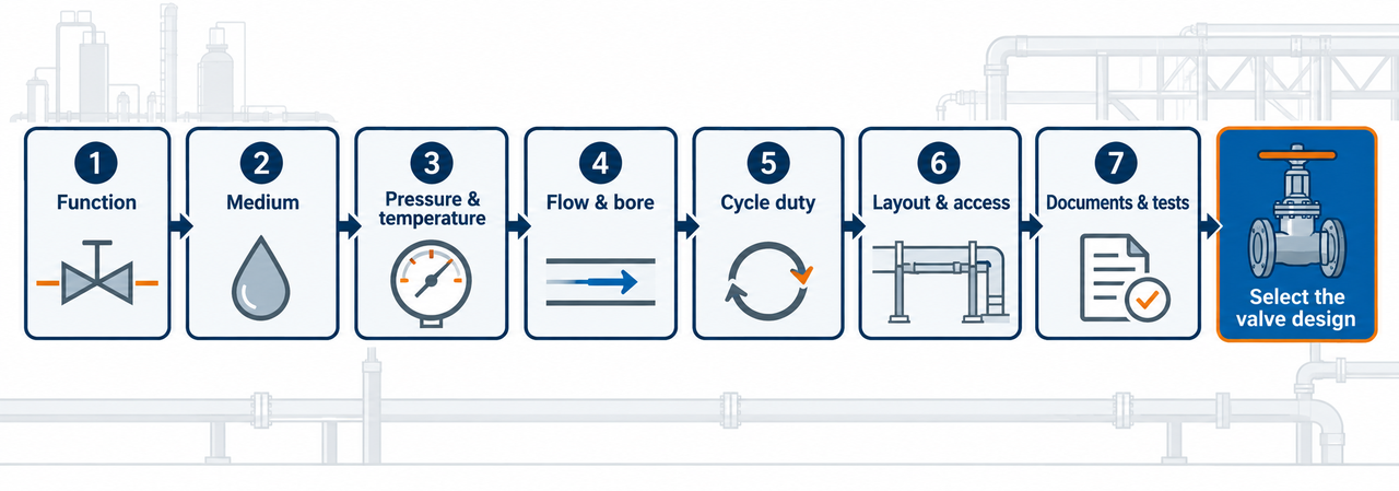
Selection begins with the work the valve has to perform, then narrows through the conditions that can disqualify a construction.
Define the function. Is the valve isolating, diverting, protecting, bypassing, venting, draining, shutting down in an emergency or truly modulating? A valve cannot be selected correctly while the function is still described only as “for water” or “for steam.”
Describe the medium. Name composition, concentration, solids, fibers, viscosity, corrosive components, temperature, cleaning medium and stagnant conditions. This is what allows a supplier to discuss materials, seats, packing and contamination risk.
State pressure and temperature. Give normal, maximum, minimum, start-up and upset values. State the differential pressure across the closed valve, because that can change shutoff and actuator requirements.
Check the hydraulic duty. Provide pipe size and schedule, flow range, allowable pressure drop, flow direction, pigging or cleaning requirement, and whether the valve will ever be partly open. Compare the actual bore, not only the nominal size. If reverse flow could damage equipment or change the isolation scheme, define the check function separately and compare the relevant check valve designs; an on/off gate or ball valve does not provide automatic non-return protection.
Specify operation. Record cycles per day, required open/close time, manual or remote operation, emergency action, power or air supply, fail position, position feedback and location classification where relevant.
Review layout and maintenance. Confirm end connections, face-to-face space, vertical clearance, lever or handwheel sweep, actuator envelope, lifting route, insulation and access for future repair.
Set the evidence requirement. Put applicable standards, test criteria, material certificates, inspection points, drawings, data sheets, third-party witnessing and spare-parts expectations into the RFQ. A technically complete quotation is more valuable than a fast price for an underspecified valve.
This sequence is not paperwork for its own sake. It stops a common chain of errors: a valve is first chosen by pipe size, an actuator is added later, the drawing then exposes a clearance problem, and the team discovers only at commissioning that the quoted seat or operating torque does not match the duty. Defining the job before selecting the family is usually faster than correcting an attractive but incomplete quotation later.
An operator needs to reduce process flow during changing production conditions. A gate valve happens to be installed, so it is left partly open. It appears to work until the gate and seats begin to see concentrated flow and the valve later fails to provide dependable isolation. Replacing it with a normal ball valve at a partially open angle does not solve the underlying issue; the process still lacks a defined control characteristic and a selected modulating duty.
The fix is to separate the two jobs. Specify an isolation valve for safe shutoff, then select and size a real control solution for flow regulation. This is the kind of distinction that saves more engineering time than a generic “ball valve versus gate valve” recommendation.
Suppose two suppliers quote the same nominal size and pressure class. One offer has a reduced-port ball, soft seats and a bare lever; the other has a full-port ball, a geared operator and a different test package. The lower price may be reasonable, but the offers are not directly comparable until the line's flow allowance, operating method, shutoff expectation and documentation requirement have been placed beside them. The same discipline applies to a gate-valve quote: a generic gate description is not enough to establish the gate construction, stem arrangement, packing, operator or service access that the project requires.
An experienced reviewer does not accept a conclusion merely because it sounds plausible. They ask what document, calculation or inspection record supports it. The following evidence package makes a gate-versus-ball recommendation auditable before the valve is ordered.
Evidence to request | What it proves | Why it matters |
Exact model data sheet | Design, materials, rating, ends, operator and stated operating limits | Prevents a broad catalogue claim being mistaken for a model-level commitment |
Pressure-temperature information | Allowable envelope for the proposed construction | Nominal class alone does not explain every temperature limitation |
General arrangement and face-to-face drawing | Bore, orientation, clearance, weight and connection details | Finds layout conflicts before installation |
Material and seat declaration | Wetted materials, sealing system and packing basis | Makes chemical, temperature and contamination review possible |
Actuator torque or thrust basis | Sizing assumptions at the stated conditions | Avoids an actuator that moves a new valve but stalls after real service exposure |
Test and inspection plan | Shell, seat, functional or project-required tests | Defines what “tested” means for the order |
Certificates and traceability scope | Documents included with the specific supply | Keeps project documentation from becoming an afterthought |
Spares and maintenance recommendation | Serviceable parts, intervals and field requirements | Lets maintenance assess downtime and lifecycle exposure |
Practical note: A manufacturer catalogue is valuable evidence of what product families are published. It is not a substitute for the exact model data sheet, project specification or agreed test plan. This distinction protects both the buyer and the supplier from over-reading a general product page.
A quotation needs another pass when it gives a nominal size and a price but is silent on the bore, seat material, pressure-temperature basis, end connection, operator, test scope or documents. None of those omissions proves that the valve is wrong. They do mean the buyer cannot yet tell whether two offers are equivalent. A sound comparison keeps the process data beside both quotations, then records every design difference before procurement treats the offers as interchangeable.
Use this checklist before comparing prices. It helps engineering, procurement and maintenance confirm that quotations describe equivalent valves.
RFQ item | Why it changes the selection |
Medium and full composition | Determines corrosion, solids handling, seat, trim, packing and cleaning requirements |
Normal, maximum and upset pressure/temperature | Determines rating, materials, shutoff duty, torque and thermal considerations |
Pipe size, schedule and end connection | Determines fit, bore, face-to-face dimension and installation scope |
Required flow and allowable pressure drop | Prevents a nominally correct valve with the wrong bore or hydraulic performance |
Valve function and partial-opening duty | Separates isolation from true control service |
Cycling rate and required closure time | Determines wear expectations, operator/actuator sizing and surge review |
Manual or automated operation | Defines torque, travel, fail action, signal, position feedback and mounting |
Standards, tests and documents | Makes it possible to compare technical scope rather than labels or price alone |
Maintenance and spare-parts expectations | Identifies access needs, service strategy and lifetime cost drivers |
For a quote centred on fast isolation or a particular ball construction, begin with the documented Shinjo ball valve range. For a gate-led isolation duty, compare the specific gate valve construction against the same operating data. The supplier should be able to explain why the proposed model, materials, seats, ends and operator address the stated conditions.
Neither is universally better. A ball valve is commonly the better starting point for fast or frequent isolation and quarter-turn automation. Gate construction remains appropriate for full-open/full-closed isolation only when its layout and service duty support it. The medium, pressure-temperature conditions, cycling, bore, access and control requirement decide the final answer.
A fully open gate valve can present a straight flow path, and a full-port ball valve can also be suitable for low restriction. A reduced-port ball valve may produce a different result. Compare the actual bore, flow, fluid properties and documented hydraulic data instead of choosing from a family-level slogan.
Do not assume so. A normal gate valve should not be used for general throttling unless the design and service are specifically approved. A standard ball valve is not automatically a control valve either. When the process needs stable modulation, select a V-port ball valve or control valve around the real flow and pressure conditions.
Start with the required function. Compare a ball valve for fast quarter-turn isolation, a gate valve for appropriate full-open/full-closed isolation, and a butterfly valve when a compact large-line arrangement may be valuable. Then assess bore, disc-in-flow effect, pressure class, medium, shutoff criterion, operating system and layout. The design cannot be chosen safely from size alone.
Choose a ball valve when the line genuinely needs fast, repeatable isolation or a compact quarter-turn automation package, then verify the ball, seats, bore, materials, torque and closing behaviour. Choose a gate valve when the duty is truly full-open/full-closed isolation and the selected gate construction fits the process, access and maintenance conditions. If the valve will spend meaningful time partly open, pause the comparison and define the real control requirement. That one correction prevents a large share of avoidable valve-selection failures.
